Not Every Upgrade Is Worth It—These Were
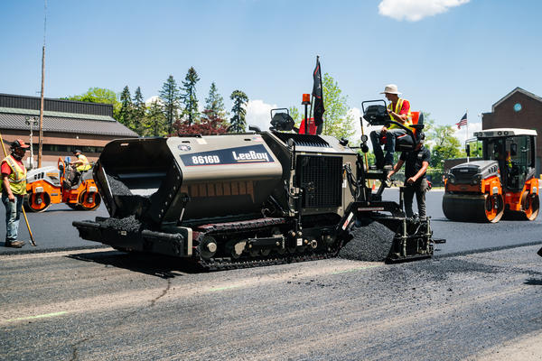
With trade shows full of new tools and features, it can be hard to sort out what’s worth investing in. Bill Stanley shares the technologies that earned their keep in the field—delivering results on real job sites, not just looking good on the show floor.

Walk a trade show like CONEXPO-CON/AGG and you’ll see no shortage of technology. Some of it looks great on the floor. Some of it never really holds up once it gets out on a real job site. And some of it is a complete game changer.

At American Pavement Specialists, when we look back at what’s actually made us more profitable over the years, it’s not hard to spot the pattern. The technology that’s worked for us is the technology that tightened up the basics and took guesswork out of the job. These are the tools that made the biggest difference.

Beyond the Spec Book: Bill Stanley’s Standards for Blue-Collar Quality Control

Getting the Grade

If you want to talk about technology that actually moved our bottom line, it starts with grade. Nothing else even comes close. You can have the best mix, the best crew, the best roller on the job, but if the grade is wrong, it all falls apart. That hasn’t changed. What’s changed is how we get there.

Years ago, getting grade right took a lot of experience. The grader or dozer operator was the guy. He read stakes, ran a transit or laser, and knew how to make water move left or right. That skill took decades to learn. If you didn’t have it, you paid for it later—in drainage problems, callbacks, and pavement that didn’t perform the way it should.

Today, we have technology that backs that experience up. On new construction, 2D and 3D grade control systems—whether it’s GPS- and laser-guided setups or systems from Trimble and Topcon—are total game changers. At American Pavement Specialists, that means running Topcon controls that come integrated directly from the factory on our equipment. The machine is reading the grade and helping the operator hold it. You still need someone who knows what they’re looking at, but you don’t need a 30-year veteran just to hit a 2% slope anymore. The guesswork is gone, and the work gets done faster and more consistently.

On existing construction, the payoff shows up in profiling and milling. Instead of cutting a flat two or three inches everywhere, the machine can adjust on the fly. It can take nothing in a low spot and more where it actually needs it, while still holding crown and slope. That matters, because every inch you don’t over-mill is asphalt you don’t have to buy back. That’s real money—material, trucking, and time.

Grade isn’t about making it look pretty. It’s about drainage and performance. Water that doesn’t move becomes a problem fast, especially in freeze-thaw climates. Puddling turns into ice. Ice turns into liability. Getting the grade right from the start avoids all of that, and today’s technology makes it a lot easier to do that consistently.

The machine doesn’t replace experience. It backs it up. You still need judgment, especially on older sites where there are no plans and nothing is documented. But when you combine experience with the grading and profiling technology that’s built into equipment today, you get better results with less waste. That’s why getting the grade right is still the foundation of everything we do—and the first place technology really started paying us back.

Prepare for Playoffs to Start Next Season Strong

Quality Pays or Costs You

We’ve always had to hit specs. That hasn’t changed. What has changed is how those specs affect pay. They’re no longer just pass-fail. Today, performance is tied directly to money. Hit the numbers and you can earn incentives. Miss them and you lose money.

The way contractors get paid has also changed the way contractors talk. Years ago, success was measured by the size of the work you did. Now the bragging rights come from hitting the numbers. Quality shows up on the check, so quality is what gets talked about.

Technology made that shift possible. For example, the grading and profiling tools we talked about earlier set a higher standard for smoothness before we ever pave. Truck-tracking software makes it easier to keep material moving, prevent stops at the paver, and reduce screed settlement. Paver-mounted thermal profiling helps catch temperature issues early, reduce segregation, and support better density. Those tools all help put us in a better position to achieve our incentives.

But for us at American Pavement Specialists, the biggest impact has come from intelligent compaction. Veteran operators finally get confirmation of what’s happening under the drum instead of relying only on feel, and many realize they’ve been over-rolling or missing areas they never would have questioned before. For younger operators, the technology reinforces proper rolling patterns faster and more consistently, without lowering expectations. Either way, density gets tighter across the mat, with fewer surprises when testing starts.

How to Know When a New Hire Is Worth the Extra Effort

Instant Feedback While the Mat’s Still Hot

Experience still runs this industry. Always will. What’s changed is that now we can back that experience up with information, and we can get that feedback while the job is still happening instead of after the fact.

Years ago, you paved, you rolled, and you moved on. If there was a problem, you might not find out until cores came back or someone called weeks—or years—later. Today, a lot of that information is available in real time. Tools like GSSI’s PaveScan technology, now being incorporated directly into OEM equipment, allow crews to see density-related data across the mat instead of waiting for cores to come back.

That instant feedback matters because it lets you make decisions on the job site. If something isn’t right, you can fix it while the mat is still workable instead of hoping it passes later. That might mean adjusting rolling patterns, changing timing, or stopping the job and making a call before the problem gets locked in.

It also changes how we communicate with owners, inspectors, and engineers. Instead of explaining why something should be right, we can show them. We’re not defending a gut feel. We’re backing up experience with information.

Estimate Smarter: 6 Steps Before You Bid a Job

Ergonomics, Machine Control, and Staying in the Seat

Some of the biggest technological improvements we’ve seen over the years are also the least flashy. Ergonomics, machine control, things like that don’t get a lot of attention, but they matter because they make it easier on the people running the equipment.

Older equipment was hard on operators. No suspension. No real climate control. Fighting steering and controls all day. By the end of a shift, you weren’t just tired—you were worn out. A lot of guys didn’t make it to retirement because their bodies gave out first.

Today’s machines are completely different. Better seats. Better visibility. Climate control that actually works. Push-button controls instead of muscling joysticks all day. Pavers that stay straight with the touch of a button instead of the operator fighting the machine while the truck pushes. That doesn’t just make the job nicer—it makes the work better.

When an operator isn’t exhausted, the machine runs smoother. Screeds stay steadier. Joints stay straighter. Transitions are cleaner. A paver that tracks straight feeds the screed better, and that shows up immediately in the mat. Small things add up fast.

Ergonomics also changes who can do the work and how long they can do it. Younger operators get comfortable in the seat faster. Older operators stay productive longer. That reduces turnover, protects experience, and keeps skilled people where you need them—on the machine.

Bill Stanley’s Top Tips for Estimates, Part 2

Safety Technology That Actually Matters

Safety technology today is better than it’s ever been, and a lot of it doesn’t get talked about because it isn’t flashy. But it matters. It matters because one mistake, one bad moment, can shut a job down or put a company in a bad spot fast.

Basic things have gotten a lot better. Braking systems on machines and trucks. Visibility. Defrosters that actually work. Mirrors you can see out of. But newer technology takes it a step further. For example, machines that can automatically stop if something is detected in front of them.

Inset: On the trucking side, we’ve begun using dash cams and backup cameras to protect our drivers and the company. They’re not there to spy on anyone. They’re there because when something happens, it’s usually assumed the truck is at fault. Video changes that conversation quickly and keeps bad situations from getting worse.

At the end of the day, safety technology is really about risk. Keeping people from getting hurt. Keeping jobs moving. Keeping insurance and liability from blowing up. It doesn’t replace awareness or common sense, but it helps limit the damage when things don’t go perfectly.

One of the biggest changes for us didn’t happen behind the screed. It came from simply knowing what our equipment is actually doing. Not guessing. Not assuming. Knowing.

Most machines today come with tracking built in. We can see hours worked, idle time, service intervals, and fault codes without walking across the yard. If a machine runs eight hours and half of that is idle, we see it right away. That changes behavior and conversations fast.

Maintenance is where this really pays off. Instead of waiting for something to fail, we know when a machine needs service. In some cases, the manufacturer will call us before the operator even knows there’s an issue. That keeps jobs moving and avoids small problems turning into big downtime.

Truck tracking fits into that same visibility. We can see routes, speed, braking, and idle time right on a phone. That’s not about babysitting drivers. It’s about safety, wear and tear, and liability. How a truck is driven shows up later in maintenance costs and risk, whether you track it or not.

Inset: Technology has streamlined the office side of our business. With today’s apps, things like mileage tracking, fuel tax reporting, and job documentation are push-button instead of paperwork and guesswork. An owner or project manager can see what they need right on their phone, without a big office staff chasing numbers.

How to Dial in Efficiency for Maximum Production

Final Thoughts

You don’t have to invest in every new technology that comes along. Technology is coming so fast right now that if you chase every new button or upgrade, you’ll either go broke or end up being the guinea pig testing out the bugs.

At American Pavement Specialists, we’ve tried to be smart about it. Sometimes we wait. Sometimes we invest in new machinery not because the old stuff is worn out, but because we know the new features on the equipment are worth it. When a technology is ready to earn its keep in our fleet, that’s when we buy it.

As technology continues to advance, we plan to apply that same thinking. But no matter how far it goes, I know technology will never replace the experience on our crew. To us, the value of these tools is that they support the people in the seat, strengthening the crew you have instead of substituting for it.

Bill Stanley owns American Pavement Specialists, Danbury, Connecticut, with his wife, Colleen. Stanley has more than 50 years of experience in the asphalt industry.
Using the Screed Effectively: Part 2

Use the rear mount vibratory screed effectively in asphalt paving

Starting with the February issue, we began a bit of a review on the three most common types of screeds we use in asphalt paving. The first installment included an overview on the three most common types of hydraulically extendable asphalt screeds, along with a bit of a deep dive on the European style tamping screed versions (which are always going to feature rear mount extenders) that are very common in Europe and certain other regions in the world. The tamping screed is rarely used in the United States and Australia for the thinner asphalt overlays, mill and inlays, and generally thinner single layer asphalt passes that differentiate the U.S. approach to asphalt paving versus that of Europe.

To recap, Europe tends to pave much thicker layers in a single pass than the United States and relies very much on imparting a significant proportion of compaction to the asphalt layer early in the process, directly at the paver screed in the form of single or duo-tamp high compaction screeds.

Control the Feed to Control the Screed

These high compaction European style tamping screeds have a relatively limited presence in the U.S. market other than in specialist, niche applications such as roller compacted concrete and cement-treated base or very thick layers required to be placed in a single pass.

As most asphalt paving in the United States and Australia is usually placed in 2- to 3-inch compacted layers at a time, a vibratory screed is usually the most used tool in these regions. It is most often capable of delivering acceptable and achievable levels of density.

Let’s look at the first of two common versions that we see on most any U.S. paving site—the rear mount (extenders are behind the main screed unit) vibratory asphalt screed.

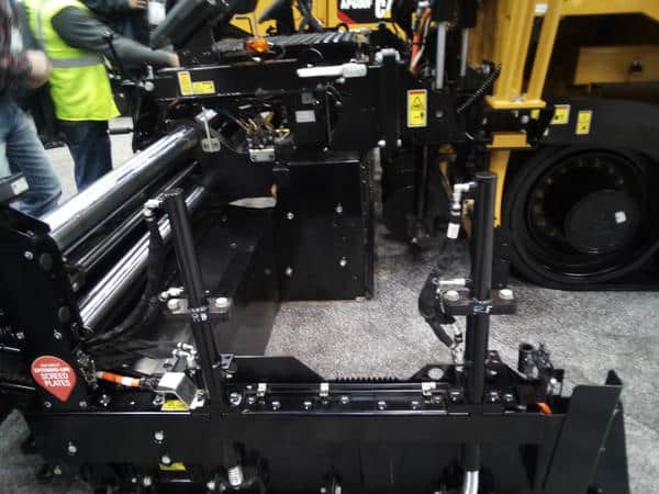
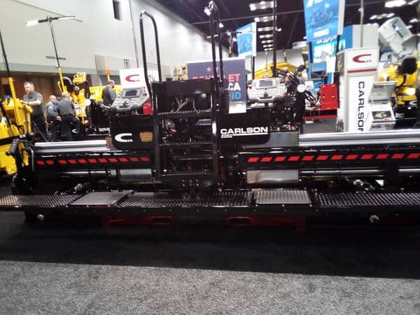
The Carlson EZR2 vibratory rear mount screed includes heavy duty large diameter chrome guide tubes to avoid flex in the screed at wider paving widths.

When to use the rear mount screed

These typically feature on a lot of high specification work such as airports, racetracks, and mainline or interstate paving where density and a consistent mat texture are important.

Because a U.S.-style rear mount vibratory screed is generally a heavily built, strong and stable unit, it usually places a homogeneous and tight mat texture across the entire screed width even at fully extended widths. The extender units are frequently attached to the main screed assembly with massive, 4- or 5-inch-diameter chrome guide tubes with solid guide tube bushes to help prevent flex in the extenders at maximum width and when additional screed sections are installed to increase the overall paving width. Generally, a rear mount vibratory U.S.-built screed is seen in heavy highway applications where paving runs are of a fixed or constant width, and which are less variable in width than those typically encountered in commercial type paving and inner-city streets.

In this application, they typically perform well at lifts of 2 to 4 inches thick. Most often the screed plate widths of both the main and extenders are symmetrical. For example, an 8-foot basic width, rear mount vibratory unit can usually hydraulically extend out to double its closed width to 16 feet at the flick of a switch (before bolting on additional screed sections). This is kind of convenient and pretty nice to be able to do on the fly.

How to Maintain Your Screed

Further, because of the design of a rear mount screed, as the paver moves along, the material being augured out from the ends of the main screed naturally flows into the void created with the extendable sections located behind the main screed. This essentially means you can most often get away with not having to install additional bolt-on auger extensions and tunnel guards. However, the drawback is you end up carrying a fairly large head of material versus a front mount design, and as we will discuss further on, this can create some operational challenges.

Another feature the rear mount vibratory U.S. screed often offers is the main screed plate depth (front to back dimension) in relation to that of the extenders. Most heavy highway rear mounts seem to have at least 16 inches deep main and extender screed plates, with the majority tending to be in the 18-inch or even 19-inch range.

There are advantages and disadvantages with this design. Having a heavy, solid and very stable platform with deep screed plates invariably leads to a very tight, dense and pleasing “ironed” mat texture across the full width of the screed, with generally consistent mat densities at all widths.

The downside of deep screed plates is the longer they are (front to rear), the more volume of excess material you end up carrying. Once you have created a large amount of material, it becomes difficult to quickly (or effectively) reduce the size of this pile of mix on the fly.

10 Screed Setup Steps for Better Mat Control

For example, if you were paving along quite happily, doing a great job, then encounter an obstruction such as a narrowing from a concrete pedestrian refuge or traffic calming measures approaching an intersection where the available width to be paved is reduced, it is simply not very easy, quick or practical to somehow “get rid of” that large pile of mix sitting in front of the extenders. It wasn’t really causing too much of an issue on the constant-width sections of work. It’s not so easy to reduce that pile by turning off the conveyor feed to the side affected by the obstruction, as what usually happens is the outer corner of the main screed and even the main screed will become starved of material well before you have made much of an impact in reducing the extender pile.

Not only that, given that it’s a fundamental rule of thumb in proper paving practices to maintain a consistent, balanced head of material across the full width of the screed at all times, compromising that known requirement is basically a cardinal sin and doesn’t do much for both your overall mat quality, nor the ability for you to control the screed. Remember our golden rule from the January issue: “Control the feed, and you control the screed.”

Another problem issue for commercial paving contractors trying to use a rear mount highway class design screed on jobs with a lot of short runs is, by design a rear mount requires quite a lot of additional material in the area outside the ends of the main screed and the extenders. It’s a void. Basically, it takes quite a lot of material to be carried in that area just to float the extenders. If you have to keep stopping every 100 feet to pick up and set up adjacent to that short pull to place a series of consecutive passes, it becomes time consuming and labor intensive to continually pick up a substantial pile of mix at the end of each pass. That’s usually why you won’t see too many highway class rear mounts in commercial work.

How to Manage Screed Plate Wear

There is a further peculiarity unique to all rear mount screed designs that doesn’t predispose them particularly well to tricky sites that feature a lot of obstacles to navigate or sites with sharp curves and concrete work. This is the fact that because the extendable sections are located behind the main screed, the length of the side plates (or end gates) is typically around twice the length of a front mount screed.

What this means in practical terms is that you are not able to trace an end gate around a sharp radius particularly well with a rear mount on account of its overall length. There’s going to be a lot more hand work required around obstructions such as light poles and the like. This is not a dig at or a criticism of the rear mount design. In the right application, these screeds shine and can deliver excellent outcomes when set up and operated correctly in their “natural habitat.” As we discussed in the February installment, we want to select the right screed for the right project at the right parameters.

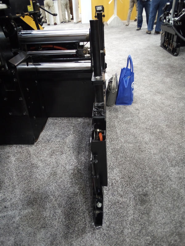
This rear mount vibratory U.S.-style screed shows the location of the hydraulically extendable sections behind the main screed.

Real-world use

Constant width, wide open highway or interstate work, placing multiple lane widths at a time, and high spec airport work is where the rear mount vibratory unit really shines and is most in its element.

There are a number of very capable and popular U.S.-made rear mounts out there that deliver, such as Caterpillar’s SE50 V, SE60 V, SE60 V XW, Carlson’s EZR2 08 and 10, Dynapac’s Mat Master 16R and 20R along with the identical Bomag U.S.A. Stretch 16E and 20E well proven Cedarapids design legacy model, as well as Vogele’s VR 600 and newer 8-foot VR 500-3 V (which I got to inspect at World of Asphalt in March 2025 and was pretty impressed with). In my opinion, these are all fairly well proven, solid platforms that could be considered industry standards.

Further, Astec/Carlson have recently released a new 8-foot and 10-foot heavy highway class rear mount platform—the EZR3 08 and EZR3 10. Given that both Astec/Roadtec and Caterpillar have both had the inventor of the modern day fully floating asphalt screed as we know it through the Barber-Greene line in their respective history, it is sure to have proven design philosophy in its pedigree. (Astec acquired the Barber-Greene brand in 1986, then on-sold it five years later to Caterpillar in 1991, who still hold ownership of Barber-Greene paver branding).

How to Figure Fluff Factor with a Smooth Screed

But as always, there can be an exception to the rule, and I’m going to touch on that next.

Recently, I have noticed an interesting new commercial type rear mount platform Caterpillar has designed and built for its new medium sized commercial class 8-foot AP455 and 555 models. The platform seems to have been intentionally conceived to try and address many of the issues I alluded to earlier that typically disqualify most rear mounts from being the screed of choice or at least seriously considered by commercial contractors.

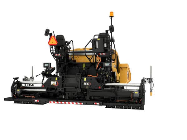
The new model SE47 V is an impressive looking, compact and low-profile design, 8-foot commercial class rear mount screed. It has quite a short 12.8-inch main and extender screed plate depth measurement, which should mean it is a lot easier to manage the volume of material on commercial work and require shorter take off pads. Plus it has quite a low overall operating height compared to most typical highway class rear mount designs. This should mean it is better for screed operators to see into the auger chamber, making it easier to monitor and manage the all-important head of material. It would currently appear to be the only purpose built, compact rear mount design oriented toward commercial paving, from what I can see. I’d be interested in seeing how it performs, and I will be watching with interest.

This newer SE47 V vibratory screed from Cat, mounted on an AP455 paver, offers a low-profile design as a commercial class rear mount screed. It features a 12.8-inch main and extender screed plate depth measurement, which should mean it is a lot easier to manage the volume of material on commercial work and require shorter take off pads. Photo courtesy of Caterpillar

Let’s talk in Vegas

Did you pick this up while you’re at the CONEXPO-CON/AGG show? I’d be happy to talk more about these positives, negatives, and best use cases, as well as other asphalt paving topics during my Ask the Expert session at the AsphaltPro Magazine booth GL30901. I’ll be at the booth on Wednesday, March 4, from 1:30 to 3:30 p.m.

In the next installment of this short series, I’ll drill down on that traditional North American commercial paver contractor’s weapon of choice: the front mount vibratory hydraulically extendable screed.

Benjamin Everett is the owner of About Asphalt Ltd., and has worked in the asphalt industry for nearly four decades. For more information, contact him at bjeverett@aboutasphalt.co.

Haskell Lemon Preserves Route 66, With Incentive

Route 66 Centennial pavement preservation celebration

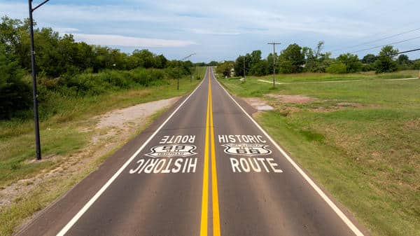
As our nation celebrates its 250th birthday, its most famous highway celebrates its 100th. To recognize both, AsphaltPro Magazine is proud to highlight a 2025 pavement maintenance project on Route 66 near Chandler, Oklahoma, in which Haskell Lemon Group, headquartered in Oklahoma City, received a smoothness incentive for their good work. Here’s how they improved conditions on that stretch of the Mother Road.

Contractor’s New Museum Offers Glimpse of Route 66 History

Know Your History

Oklahoma Department of Transportation (ODOT) District 3 let the patching, leveling and surfacing project in spring 2025 to preserve 12 lane miles of a section of Route 66 outside Chandler. This involved milling part of the project, placing a ¾-inch leveling course and 1 ¼-inch surface course over all of it, and installing guard rail. None of this work was foreign to Haskell Lemon crews, which have performed maintenance and preservation along this historic roadway for decades.

Jay Lemon, president of the company and this year’s chair of the National Asphalt Pavement Association (NAPA), shared that they’ve been proud to work on sections of Route 66 within the state for as long as he can remember. In 2015, for example, they handled a project on the business road near Hydro and Weatherford.

A significant project he’s proud of took place in 2001 near Geary. For that one, the crews did more than repair the original concrete highway; they contributed to the nation’s history about this road.

Foamed Asphalt Preserves Route 66 in Missouri

“We removed six concrete slabs to be installed in the Smithsonian,” Lemon said. “We had to be gingerly with the process.” He explained that the team cut and removed the slabs, lifting them onto flatbeds for transport to Washington, D.C., where they are on display today.

For the Main Street of America, crews go where the road takes them. In 2022, Haskell Lemon performed a mill and overlay in the middle of a town. In 2020 and again in 2023, they worked on a section designated 66 north of Oklahoma City. It’s a proud moment to win a bid on the famous route.

Lemon explained that maintenance of Oklahoma’s stretch of Route 66 in the past typically consisted of bringing the highway up to new traffic conditions. “It was a 20-foot-wide, original concrete-paved road, and some sections are still that. But that’s way too narrow for today’s traffic. The majority is widened and replaced, so it’s a more durable product. Maintenance and widenings add 3 to 5 feet to either side and overlay it with asphalt.”

Celebrate our Shared History: https://theasphaltpro.com/route-66-road-construction/

Many of the preservation projects have seen the original 20-foot-wide, concrete-paved road repaired, widened 3 to 5 feet to either side, and overlaid with asphalt. Photo courtesy of Haskell Lemon

Maintain Your History

And that’s the structure his team worked on in 2025; a 24-foot-wide asphalt surface.

“In addition to the pavement patching and overlays, we installed widenings for approximately 40 locations to add guard railing, as a safety improvement,” Lemon shared.

In all, they placed about 19,700 tons of ODOT Type S-5 mix, which requires a PG64-22 binder. They included reclaimed asphalt pavement (RAP) for the ¾-inch leveling course. They produced this in their stationary CMI drum mix plant, averaging production temperatures of 320°F, located about 40 miles from the project.

“We call it our East Plant,” Lemon shared. It’s rated for 300 tons per hour, and for this project, “We averaged 150 tph.”

For paving, the crew used a CAT 1055F machine. “We utilize a CAT conventional paver with an Integral Spray Paver system added to it,” Lemon said. “The spray paver has been used on other US-66 projects, but this one was conventional paving with tack coat applied by distributor truck. We were able to maximize the smoothness incentive on this contract thanks in part to the grade/slope automation.”

Delta Brings Larry H. Lemon Award to Missouri

“We didn’t consistently utilize thermal mapping on this project, but did use a transfer vehicle for best quality and consistency throughout the whole job. We were seeing 290-310 degrees F behind the screed.” He reported the mix behaved normally at those temperatures for them.

To get compaction and build the joint, they used industry best practices.

“We paved two each, 12-foot-wide lanes. We would match centerline joints within one to two days to ensure that we could provide the best joint possible, before degradation could potentially occur. We utilized a combination of CAT double drum and Dynapac double drum rollers in our rolling train.”

The rolling team was exemplary in their work.

“No intelligent compaction technology was used. We utilized portable density measuring devices to monitor and ensure quality compaction. Our gauges were showing acceptable, and no cores were required as the lifts were too thin to utilize that practice.”

Ten DOTs Garner Perpetual Pavement Awards with Asphalt

Instead of cores, the gauges used by Haskell Lemon and ODOT proved the team’s success. Lemon shared that they used an “ODOT-approved rolling pattern with verification occurring every day. This was successful for both teams.”

“They completed all of this work with zero accidents, internally or to any of the motoring public,” Lemon said proudly. “This is huge considering the tight working conditions and the rural nature of the project,” which included flagging operations on the two-lane interstate. “We were pleased with how the project was planned and performed.”

Considering the high-profile nature of the historic roadway, having a successful project executed with no accidents is its own reward. Add to that receiving an incentive for its smoothness, and the Haskell Lemon team has even more to be proud of when pointing to their participation in the Mother Road’s centennial celebrations this year.


Share Your History

Has one of your asphalt crews worked on Route 66? Share that with the wider asphalt audience!

Reach out to Sandy Lender at AsphaltPro Magazine so we can write about your project and what that project meant to you. Email sandy@theasphaltpro.com

And if you’re reading this while at CONEXPO-CON/AGG, stop by booth GL30901 to chat in person.

Northern Improvement Smooths Out National Park Paving Challenge

Northern Improvement smooths out Theodore Roosevelt National Park paving challenge

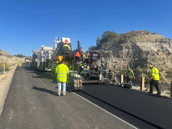
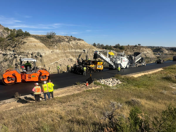
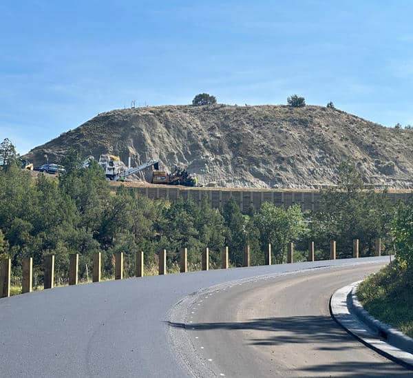
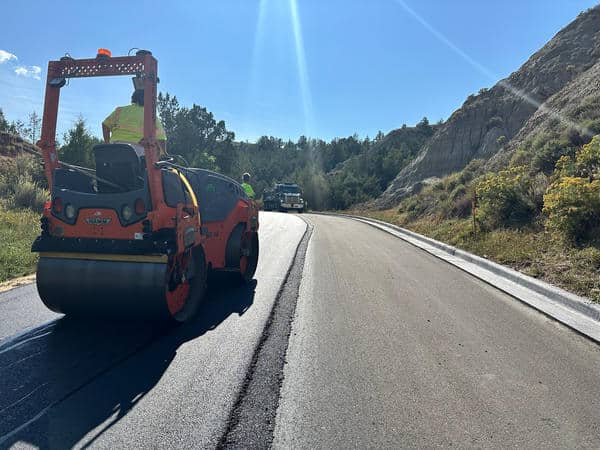
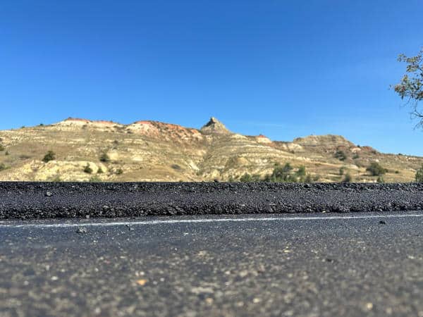
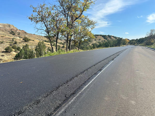
From accommodating a prairie dog town to discovering soft subgrades, the team at Northern Improvement Company, Dickinson, North Dakota, had their work cut out for them when they got the go-ahead to pave a winding path up and down 6 miles of South Unit Scenic Loop. With incredible patience and skill, they put down two 2-inch lifts of Superpave mix with 1% lime to provide a new road for visitors to the Theodore Roosevelt National Park.

As our nation celebrates its 250th birthday this year, it’s an honor to highlight a challenging yet successful project in one of our national parks. Congratulations to the Wagner and Northern Improvement Company teams for making the South Unit Scenic Loop in the Theodore Roosevelt National Park a lovely and safer route for visitors.

Trucking had to be coordinated to deliver enough material to “pave through” curves when the crew was coming up on an area where they recognized trucks wouldn’t be able to drive past the paver. Conditions were often tight. Photo courtesy of Northern Improvement

Challenging Subbase Sets Up Delays

The project was let in 2022 with Wagner taking the role of prime contractor. The scope of the project included, but was not limited to, widening, adding slope, and performing soil-cement treatment (CTB) and full-depth reclamation (FDR) of the base in many areas, according to Bryce Wuori, CEO of Pavewise Inc., Bismarck, North Dakota. Wuori served as a consultant to Northern Improvement on this project.

“The cement-treated base was 4 inches thick in most areas but needed to be more than 6-7 inches, which halted everything,” Wuori said. “The base lift became a patching project. It didn’t turn into a mainline paving project. We put in a change-order for a prime coat on top of the gravel on the hills.”

“The soils in the Badlands are very challenging,” Cassandra Tobin said. She’s the quality control manager at Northern Improvement and worked from Day 1 on the project, preparing the mix design and seeing it placed. “Retaining walls had to be built to hold up the road structure.”

The Northern Improvement paving crew placed a 2-inch lift with the notched wedge joint system from Willow Designs on the centerline joint and a safety edge roller on the shoulder side. Photo courtesy of Northern Improvement

She explained that shortly after Wagner began work in 2022, the project became complex. “They encountered weather challenges; wet winter, wet spring, so the road collapsed in a couple places,” Tobin said. “The original paving plan didn’t happen during 2024 because of the subgrade issues.”

When it came time for Northern to begin paving in 2025, their plan was thwarted again by subgrade issues. “We started paving in June and started encountering issues with the subgrade almost immediately.”

If you’re in Vegas, meet with Bryce Wuori during his Ask the Expert session, Thursday, March 5, from 9:30-11:30 at Booth GL30901 during CONEXPO-CON/AGG.

They demobilized before the July 4 holiday, so the prime could repair a section of the cement-treated base. Northern returned to pave in August 2025.

Tobin said the use of a material transfer vehicle on this project helped immensely with improving the ride results. Photo courtesy of Northern Improvement

“A lot of it was only 4 inches of CTB, and it just wasn’t enough structurally to hold up construction traffic, especially with those types of soils,” Tobin said. The first section of roadway had thicker portions of CTB and FDR, she explained, but the paving crew ran into a problem when they got past that first section.

“Once we got to the top of the first hill, we found soft spot after soft spot. Our equipment would sink. Wagner would dig down, put fabric in, rework it. We ended up putting some asphalt in the patches in the subgrade itself. We had to do a lot of skipping around and changing where we were going to pave that day…”

She described the first lift’s execution as paving a quilt, rather than one ribbon of highway.

Prime Contractor Wagner built retaining walls in addition to treating the subbase prior to turning the project over to Northern Improvement for paving. Here we see the paving train, which included a Shuttle Buggy to deliver material to the tracked paver. Photo courtesy of Bryce Wuori

“We had different sizes of patches spread out all over the place.”

As you can imagine, this start-and-stop patching was frustrating for a paving crew who planned to get in and pave. “It was very hard on our crew. We’re very quality oriented. It does wear on you, day in and day out to skip a section, or we’d try a section, and it would fail.”

Because of the initial approach they had to take, “a lot of the days were patching days,” she said. “There were multiple patch areas that we ended up having to pave multiple times. That type of paving is labor-intensive. It tied up our plant at the same time. This is a lime mix design. A lot of the projects wouldn’t approve that same mix.”

To create the Superpave ½-inch virgin mix with 58S-34 asphalt binder and 1% lime, the parallel flow hot-mix asphalt (HMA) plant needed some modification. “We had to add a lime silo and pugmill to our normal set up for this project,” Tobin said.

But there was a light at the end of the tunnel.

“Once we got that bottom lift down, everything started looking a lot better. Once it was covered in asphalt, the top lift went so much easier.”

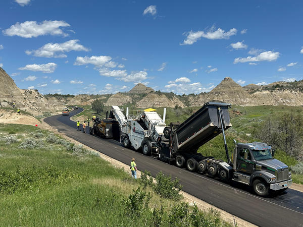
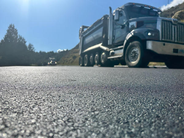
Haul truck drivers were taking it slow and being extra careful delivering mix to the paving train due to the curvy road interrupting communications and the presence of visitor and pedestrian traffic in peak tourist season. Photo courtesy of Bryce Wuori

Coordinated Trucking

The mobile plant providing the specialized mix was set up at Northern Improvement’s South Heart, North Dakota location. Plant Operator Paul Byron, who has worked for the company for almost 25 years, was averaging 180-200 tons per hour at production temperatures of 318-335°F.

This location gave the haul trucks a travel time to the beginning of the project of just over an hour. But their journey at that point was far from over.

“Our plant site is fairly close, but it takes the trucks about an hour to get in there,” Tobin said. “It was peak season for tourists, and you never knew when you’re going to come around a corner and someone’s going to be standing in the middle of the road taking a picture.”

The terrain, coupled with tourist and pedestrian traffic, meant coordinated communication was essential for mix delivery. Due to the sharp buttes and twisting curves, radio signals were often interrupted, making it difficult to get messages back and forth. To combat this, the team set up a relay system for communication. Tobin called it “traffic control for our construction traffic only.” They placed one person at the front of the construction zone, someone in the middle, and someone at the moving paving train to keep the one-way truck traffic in motion. Tobin explained that the team would plan ahead to have enough trucks deliver material to let them pave through winding sections when it was obvious space would be tight.

It took incredible coordination and communication to bring material to the paving zone amid the hills and curves. Photo courtesy of Bryce Wuori

“Sneaking trucks by the paver was sometimes not possible,” she said. “There’s nowhere to turn around. Radio traffic was difficult because of the terrain, so we were keeping track of where everything was at all times. Some areas did have curb-and-gutter. We had to plan out to have enough trucks to get us through an area of curves if we knew we couldn’t get trucks past the paver.”

It came down to communication, caution, and planning. “It was an existing low-speed road, but the amount of coordination it took was like a racetrack project,” Wuori said.

“There was a lot of walking—you parked where you started the day—there’s not much for parking, not much for turning around, not much room for extra,” Tobin said.

Due to the terrain, the rolling train didn’t use intelligent compaction with the Hamm HD 120i V10-2 breakdown roller. Cassandra Tobin shared, “With jumping around so much, it just wasn’t feasible. We used Density+ by Pavewise to track our density results from our nuclear and non-nuclear density gauges.” Photo courtesy of Bryce Wuori

Smooth Paving

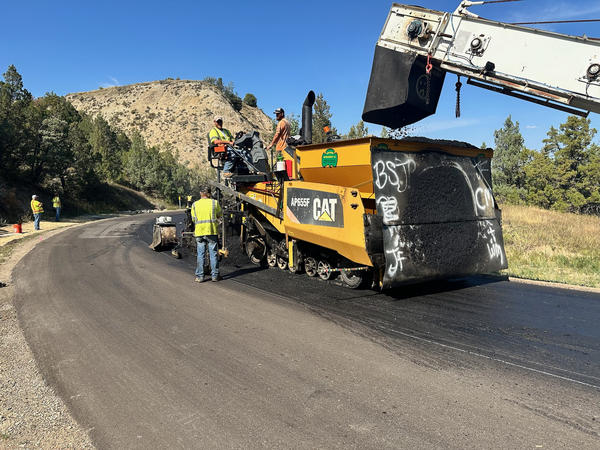
When trucks reached the paving train, they fed a Roadtec SB-2500e material transfer vehicle (MTV), which fed a CAT AP655F paver equipped with the notch wedge joint maker from Willow Designs. They placed two 2-inch lifts across the total top roadway width of 22 feet in 11-foot pulls.

The mix temperature coming off the screed averaged 280-300°F and performed well for the crew. “The mix was easy to work with, but challenging in areas that were difficult to roll (tight curves, steep grades),” Tobin shared.

To achieve compaction, the team used a Hamm HD+ 120i VIO-2-HF with both drums in oscillation mode in the breakdown position. Tobin reported average densities of 89-90% in the breakdown zone, which was essential for achieving the percent within limits (PWL) spec on the project.

“The PWL density spec was challenging,” Tobin shared. “We had to achieve similar densities on the base lift and top lift, as well as the edges and center of the mat. Generally, you see a lot of variability in density on tight curves and up/down hills. We were able to keep consistent density throughout the project using a combination of technology and technique. We had a quality control technician, Kim Bumgardner, monitoring density with a nuclear density gauge throughout the project. She is a great roller operator herself, and using her experience and the data she was collecting, she was able to see when any changes needed to be made to the rolling operation.”

The Shuttle Buggy delivers material to the paver, helping the crew maintain smooth production around tight curves and hills. Photo courtesy of Bryce Wuori

One technology, intelligent compaction (IC), wasn’t feasible on the project due to the terrain, thus good equipment, best practices, and other technologies came into play.

“The big part of technology was that Hamm roller itself,” Tobin explained. “We could adjust the drums if we needed to either oscillate or vibrate, and the settings can easily be swapped around if needed. It is kind of like having several rollers in one. We didn’t set up Intelligent Compaction on this project because of the terrain. With jumping around so much, it just wasn’t feasible. We used Density+ by Pavewise to track our density results from our nuclear and non-nuclear density gauges.”

A combination, smaller, intermediate roller with rubber tires on the back was used in the intermediate position; a smaller, steel drum was in the finish position.

“The Hamm oscillation in breakdown was key in this terrain,” Tobin said. “It was still challenging getting up close to the curbs on such tight curves. The guys had their work cut out for them…The smaller rollers were very beneficial to us in this terrain.”

In addition to the PWL spec, the team had a two-part ride spec to consider and random core sampling to arrange.

“The ride spec for this job was especially difficult considering it is a 25-mph road with very tight curves and a lot of curb transitions,” Tobin shared. “That was further complicated by all the soft spots and subgrade repair areas. The spec includes two parts. One for the overall ride and the other for localized roughness (each bump). The use of the [MTV] helped immensely with improving the ride results.

“The asphalt sampling for testing was truly a group effort that required quick coordination,” she continued. “The inspectors would give us short notice when coming up on a sample. The logistics of getting the testers and the people needed to be able to pull the sample from the mat behind the paver was very difficult given the challenging terrain, lack of cellular coverage, and the congested narrow roadway with extremely limited parking. Terracon had a QC team made up of multiple testers, which were always on site or transporting samples back to the lab during paving to make this happen. It was an impressive, coordinated team effort.”

Side view and detail of the notch wedge joint build. Both photos courtesy of Bryce Wuori

“They did a really good job, especially with the level of difficulty,” Wuori said. “They held to all FHWA specs of density and ride.”

The result was approximately $200,000 bonus on material and density for Northern Improvement, and a fresh new road for the National Park Service and the visitors to the Badlands National Park.


Prairie Dog Chatter

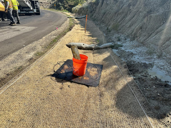
Wagner, the prime contractor for the project, placed a rodent barrier along the shoulder at the outset of the project, for the crew from Northern Improvement Company, Dickinson, North Dakota, to pave over; the goal of this system is to keep the prairie dog population from burrowing under the road, thus causing damage. When rolled out, the netting is quite flexible, making it a challenge to place an asphalt lift on top of.

Northern Improvement Quality Control Manager Cassandra Tobin described it as a “flexible wire, folded back across the shoulder.”

She explained that even though the mesh was fastened down, it tended to flex when being paved over. “It flexed and that caused some cracks. The top lift covered that.”

The flexible netting also impeded the paving sensors. “They picked up some of that chatter,” Tobin said.

But the professional crew understands paving basics and could guide the CAT AP655F smoothly through the beginning of the project. In the end, the rodent barrier was successfully installed and covered for both the pavement system’s and the prairie dog town’s protection.

Using the Screed Effectively: Part 1

Use the tamping screed effectively in asphalt paving

Starting with this issue, let’s do a bit of a review on the three most common types of screeds we tend to use. Please note, there are still certain regions that mandate and use fixed screeds. However, for the most part, the lion’s share of hydraulically extendable paver screeds tend to be in three distinct camps:

  • European Union style tamping, tamping and vibratory, duo-tamp and tamping with pressure bars
  • Rear mounted hydraulic extendable screeds with vibration (common in the United States)
  • Front mounted hydraulic extendable screeds with vibration (common in the United States)

In this first installment, I’ll focus on the European style tamping screeds, which are rare in the United States. We typically see them used in limited numbers in specialized niche markets such as roller compacted concrete and cement-treated base work.

This is the European Union style tamping screed setup. It usually has threaded bolts to adjust the screed pitch. If the crew hasn’t brought wrenches to the job site with them, this will not be an easy thing to adjust. This means many crews using this style of screed won’t adjust the screed pitch as they should when encountering a change in mat thickness.

Why do we have such a range? Why can’t one type of screed do everything? One size doesn’t fit all in asphalt paving. Consider: we don’t all perform the exact same type of work. Asphalt is as specialized and highly technical as anything requiring skill. You won’t see surgeons performing complex operations with a single, wide bladed meat cleaver. They have a variety of specialized instruments to have the right tool for the right job.

Just as surgeons or mechanics have more than one type of tool in their toolboxes and a golfer uses multiple types of golf clubs depending on what they are trying to do, so it is in the asphalt paving world.

But before we get too far into it, let’s have a quick recap on the fundamental differences between paving in Europe and paving in North America, because therein lies the key to answering this. Paving in the continental United States, Australia and New Zealand is not like in Europe.

This image shows the threaded bolts on a European style tamping screed.

In a nutshell, Europe tends to pave about half the speed of that typically seen in the United States. Asphalt lifts in Europe are usually placed much more thickly with each pass (other than the final surface layer), with a strong emphasis on pre-compaction from the paver screed via the action of tampers.

This is advantageous from the standpoint that because the paver has already done much of the initial compaction, final density is easier to attain, and there is less of a need to rely on a large flotilla of heavy rollers. This is why when we see European final lift or surface placement, they are often using only a few very modest sized 4- to 5-tonne tandem vibratory steel rollers.

The E.U.-style tamping screeds also generally plane at a lower angle of attack versus a North American type of vibratory screed (1/8-inch versus ¼-inch), which allows the screed plates to be “flatter” to impart more dynamic energy into the mix.

When to use a tamping screed

Think of your screed the way we have been taught to think of pavement preservation methods. We choose the right treatment for the right pavement at the right time. Apply that logic to the screed. We want to select the right screed for the right project at the right parameters.

There are both advantages and disadvantages to a tamping screed design compared to a standard vibratory screed. So, what is the rule of thumb when you should consider using a tamping screed over a vibratory screed?

When to Choose the Tamping Screed

My rule(s) of thumb are these:

  1. If 75% or more of your work is over 3 to 4 inches compacted depth with one lift of asphalt
  2. If you are consistently placing predominantly large size asphalt mix such as ¾- to 1-inch nominal maximum aggregate size (NMAS)
  3. If you are primarily placing roller compacted concrete, concrete-treated base, unbound granular base such as railway ballast or 1.5-inch size subbase with an asphalt paver instead of placing it with a grader
  4. If you are struggling to get the target density and/or air voids from a standard vibratory screed

Auger Prototype to Prevent Segregation

If I’m not having to contend with the above, my screed of choice is a vibratory one.

Mostly in North America, we are placing mixes in the ½- to ¾-NMAS range, in lifts of 2 to 3 inches compacted depth. Further, there is an unspoken (yet an undeniable) need for speed in the U.S. asphalt paving market.

Someone trying to use a tamping screed paver and thinking they will be able to keep up with a competitor using a vibratory screed paver on a 2-inch compacted depth commercial site with a ½-inch NMAS dense graded mix is likely to be outgunned and out paved. It’s like expecting a long distance or marathon runner to be competitive in a 300-meter sprint.

It’s not that a tamping screed is wrong or a bad idea. On the contrary, it’s an excellent tool in the right setting. Generally speaking, this rules out most tamping screeds from being the tool of choice for commercial and residential paving as well as thin overlays or mill and inlay jobs.

Control the Feed to Control the Screed

Real-world use

Think of it like this. Most tamping screeds are heavy, rigid and extremely solid in build. They are pretty much designed to be set up once, at the start of a project, and to place a deep, consistent thickness over essentially constant widths. Think airports and heavy industrial sites like ports and terminals.

In this application, they are usually the right choice and can deliver great results. If you need to get target density and consistent compaction results on high spec work with something that requires essentially a flat transverse profile, the tamping screed does it like a champ all day long. I often use tamping screed pavers, and in fact I have two of my own units, which I like. I find them predictable and a nice unit to use; in the right application that is.

Now imagine another scenario; one no less challenging but in a different way. It’s something most people outside of the industry don’t usually comprehend or appreciate. Many older, urban metropolitan roading networks feature a heavily crowned road profile that constantly changes, with a longitudinal shape that resembles a roller coaster. I grew up exposed to that sort of road type, and it’s not something for the faint hearted.

When performing pavement maintenance on these roadways, you are tasked with typically getting in and out quickly to hand the road back to the public as soon as possible. You must place a consistent 1.25- to 2.0-inch overlay (or mill and inlay as it usually is) while matching into existing misshapen concrete curb and gutter (that’s all up and down) and dodging manhole covers. Often, we have to introduce extreme + or – slope and maximum crowning from the main screed to avoid “grazing the highs” and “filling the lows” to ensure we meet the target mix quantity.

Why You Still Need a Good Rotary Depth Crank in Paving

These jobs aren’t usually about ride quality or compliance with a straightedge, because they are rarely flat. They are frequently of a transverse profile that alternates between a crown and a gulley (or swale). And just to make it even more difficult, almost always they are bid and paid on a square meter basis rather than tons, meaning if you go over the calculated mix quantity for the area paved, that extra mix cost is on you.

In my opinion, there is only one tool for a challenge like that—a North American design vibratory screed with front mounted extenders, power crown, slope and match height, and if possible, a berm builder feature. Think of models like the Blaw-Knox UltiMat 16 and 160, Carlson EZ4, and Caterpillar SE47 FM. For these “roads from hell,” these screed models can be “shaped” to the extreme road profile. That’s not typically something a rigid, heavy, inflexible tamping screed is designed to do.

As always in life, there are one or two exceptions to the rule. I have noticed Caterpillar’s heavy 3.0- to 6.0-m tamping screed model SE 60 VT XW comes standard with power crown, extender slope and match height and it appears to be the only tamping screed offered with traditional rotary depth cranks (screws) instead of the typical E.U. threaded rod type angle of attack adjusters.

Further, ABG/Ammann is offering two sizes of rear mount (single and duo tamping models) screed versions that come standard with power crown and power extender slope (+ and -) as well as match height. These are the 8-foot, 2-inch basic width VB-79/VDT-V 79 and the 9.84-foot basic width model VB-89/VDT-V 89. Both types can slope each extender +/- 10%, which is rather impressive in my view for an E.U. tamping screed. With these two brands of E.U. tamping screeds offering those very desirable features as standard, it puts them into quite a unique category. I consider them the exception to the rule. I’m watching both with some interest.

How to Set Up For a Perfect Paver Start Every Time

Let’s talk in Vegas

I think I’ve managed to articulate pretty much what I’m trying to convey via a typical E.U. design tamping screed, along with the many positives, and also some negatives it has. Bottom line—in the right application, a tamping screed is an excellent choice and delivers results. Just be sure to carefully evaluate your particular type of work to decide if it’s right for you.

I’d be happy to talk more about these positives, negatives, and best use cases, as well as other asphalt paving topics during my Ask the Expert session at the AsphaltPro Magazine booth GL30901 during CONEXPO-CON/AGG. I’ll be at the booth on Wednesday, March 4, from 1:30 to 3:30 p.m.

In the next installment, I’ll go over the traditional and common North American vibratory style screeds that we use almost every day, and do a deep dive on the front and rear mount designs.

Benjamin Everett is the owner of About Asphalt Ltd., and has worked in the asphalt industry for nearly four decades. For more information, contact him at bjeverett@aboutasphalt.co.

Building the Unsupported Longitudinal Joint

How we build the unsupported longitudinal joint

The subject I want to bring to you this month is about another long-standing issue. In my view, we have not yet properly or adequately come up with a sustainable solution to guarantee long-term joint life. I’m referring to what is known as the leading edge or unsupported longitudinal joint, which is the first pass paved on a carriageway requiring two or more paving runs side by side.

Typically, most roads I encounter (though not all) are crowned in the center on a carriageway of two lanes or more. In other words, the highest part of the road is in the middle along the centerline to provide a means to ensure water runs off it.

I understand that in some territories roads are built instead with a slope or straight grade from one side to the other, which also achieves the same result. After all, we don’t want standing water on any part of the road.

Whichever way the road is built (crowned or sloped), oftentimes it will need to be paved in two or more passes. Here we have a longstanding issue that crops up. That is the unsupported longitudinal joint (aka the “open side” or “leading edge”) that has to be compacted then matched with the next paving run. We continue to see ongoing problems of premature longitudinal joint failure.

Specifically, the problem is when we try to properly compact an unconfined or unsupported pavement edge, whether that’s a longitudinal or transverse joint, invariably it resists the compactive forces imparted from the roller in a vertical plane and tries to “squeeze out” laterally. This is a common, everyday issue all paving contractors have to contend with. We have to ensure we get adequate longitudinal joint density without distorting the edge and causing target mat depth to suffer when the material refuses to stay put.

There are various methods that have been trialed and are somewhat successful, although only a few would I consider to be the perfect solution. These include the next five ideas, which you may be familiar with, and an idea I’d like to propose from outside the box.

We have to ensure we get adequate longitudinal joint density without distorting the edge and causing target mat depth to suffer when the material refuses to stay put.

Heat the Longitudinal Joint for Improved Density

Building

You could anticipate how much “squeeze out” or lateral displacement is likely to occur during compaction and factor in that loss of depth by placing the outer 12-18 inches thicker than the rest of the mat. You do this so after compaction the pull levels out at the right finished height. This avoids a low area at the joint where water can pond and ensures finished height compliance.

If you have a screed with either a berm builder or extenders that can be sloped negatively or “up,” you can do this. I use this method and find it pretty effective.

As an example, on a 2-inch compacted mat, I might add another 10% to the outer edge. In this case that would be about ¼ inch. For those who have never done this, it might sound crazy, but it works to solve the thickness issue along the unconfined longitudinal joint. However, it doesn’t always or consistently ensure target mat density or air voids are where you want them to be. So, it’s not a perfect solution, in my view.

Wisconsin Job Exceeds Longitudinal Joint Density Expectations

Avoiding

Many contractors default to staying away from the unsupported edge during compaction until the mat has cooled off enough to be more stable. The problem with that technique is that by the time the mat has cooled off enough to become stable under the rollers, it’s oftentimes too cool to be able to achieve the required target density and air voids. I don’t recommend this method as it’s counterintuitive in my view, and in my experience not a successful methodology.

Cutting

In Europe, most tandem steel rollers are fitted with an edge cutter and pressing device to try to both confine the unsupported edge during rolling and to trim off the low-density outer edge after rolling is complete but while the mix is still warm enough to allow this. Traditionally, on U.S. airport paving projects, a “pizza cutter” or disc mounted to a grader blade has been used to cut away and waste the unsupported longitudinal joint by at least 3-4 inches.

The issues with both of these cutting methods are that they add quite a lot of additional time to the operation and waste a lot of material that shouldn’t really need to be cut off were it compacted well enough in the first place. Plus, it requires a lot of effort, energy and expense to pick up the discarded mix, thoroughly clean the cut back joint face (which can often cause the edge to be inadvertently damaged in the process with a skid steer, etc.), and then tack the entire joint face. It’s basically adding in a whole lot of extra work, time and expense you could avoid with a different joint-building method.

It wouldn’t be very difficult to create an automated longitudinal joint confinement system, without the manual steps of laboriously laying out, securing and removing a temporary joint confinement method.

How to Build a Notch Wedge Joint

Overhanging

Some pavers use certain compaction techniques such as having the breakdown and finish steel drum rollers overhang the unsupported longitudinal joint by approximately 4-6 inches to consolidate that leading edge in a vertical direction and prevent it from displacing laterally. I have used (and I continue to use) this methodology where necessary, and while it is reasonably effective to a degree, it’s not perfect. At the end of each breakdown roller pass there is a conundrum encountered when the steel drum compactor has to turn in toward the center of the pass as it approaches the screed to stop on an angle to avoid leaving a bow wave as it stops and reverses direction. In both directions as it comes inside the unsupported edge and goes back out to overhang on the return pass, I notice some degree of edge distortion can occur.

Also, although rolling while overhanging the joint is a fairly reasonable method, I find that there is still some degree of edge “squeeze out” (although a lot less than other methods) with the resultant issue of air voids and density typically slightly less than target along with a slight but observable loss of overall mat height along the joint.

Lastly, this methodology requires that the important secondary compaction stage undertaken with a pneumatic tire roller is unable to get closer than typically 8-10 inches or more from that unconfined longitudinal joint, as a pneumatic tire roller creates a significant amount of lateral compaction versus a steel drum compactor. This means that the important intermediate rolling stage isn’t able to be undertaken directly on that longitudinal joint until the second paving run is pulled. By then, the joint is often too cool to achieve additional compaction. All in all, that’s really a problem hiding in plain sight, and one I believe we as an industry need to face up to, confront and overcome.

Schellinger Construction Hits Notch Wedge Joint Density Specs

Echelon or Full-Width Paving

Obviously, the best solution to overcome the problems highlighted above is to pave the entire width in one continuous pass. This can be done with a single paver built out wide with screed, auger and mainframe extensions, or by paving in echelon with two or more pavers with a hot-on-hot joint overlap. To me, that’s an ideal solution and one I like to do if I have the resources and ability to do it.

However, as we all know, it’s not always possible to use these methods. Typically, on heavily built up urban and city streets we have to share the rest of the carriageway with motorists, preventing us from having the entire roadway to pave in one go.

There has been a lot of research, money, time and effort dedicated to understanding the dilemma we continue to see manifesting at the longitudinal joint, as well as solutions to overcome or improve the issues described above. But I don’t feel we are there yet.

There have been excellent industry articles posted online for more best practices on longitudinal joint construction, many of which are well over 10 years old. Many I would recommend are difficult to find today. Check out “How to Exceed the Long Joint Density Spec” and “How to Build a Long Joint in Cold Weather” at TheAsphaltPro.com for two more recent items. I’ve also included a variety of joint construction video links in the sidebar below. Yet we still seem to struggle with realizing consistently compliant, high quality, unsupported longitudinal joints on the first pass.

I think our industry is missing something here.

How to Exceed the Long Joint Density Spec

A Supporting Idea

Here’s a solution to ponder. Carefully look at what Japanese paving contractors do. I notice they build timber confinement along the entire length of the longitudinal joint to produce temporary confinement.

This appears to overcome all of the described issues—low joint density, missing target air voids and low finished mat depth on the edge. The very act of confining the material forces the mix to comply and to be properly compacted, which is a simple but clever idea.

Now I can already hear our U.S. paving brothers hollering at me, “But we pave three times faster than the contractors in Japan! They only pave at about 13 feet per minute, and we want to do at least 32 feet per minute or more!”

Sure, I hear you.

Solve the problem as I am. It wouldn’t be very difficult to create an automated longitudinal joint confinement system, without the manual steps of laboriously laying out, securing and removing a temporary joint confinement method. I’ve already designed it. If you want to talk about it, just reach out.

Benjamin Everett is the owner of About Asphalt Ltd., and has worked in the asphalt industry for nearly four decades. For more information, contact him at bjeverett@aboutasphalt.co.


Here are some links to videos that showcase joint construction methodology:

Part 1 of the Asphalt Institute presentation of “Best Practices for Specifying and Constructing HMA Longitudinal Joints” to UDOT University, February 2017

https://www.youtube.com/watch?v=SgPCGjw6MzY

Part 2 of Asphalt Institute’s presentation

https://www.youtube.com/watch?v=VlhMwb4mRMQ

Part 3 of Asphalt Institute’s presentation

https://www.youtube.com/watch?v=FEdHmsje71k

A 5-minute step-by-step look at the “Maryland Method Longitudinal Joint Compaction” from Marshall Klinefelter

Maryland Method Longitudinal Joint Compaction – YouTube

Timelapse video of Japanese job site begins around the 20-second mark here

https://www.youtube.com/watch?v=p2hk4qDrSbM

A Japanese paving site with wood-confined edge

https://www.youtube.com/watch?v=xlDC_VbquJA&t=6s

A Japanese paving site with endgate riding on wood structure to confine edge

https://www.youtube.com/watch?v=MgzJaXNeLms&t=6s