Sustainability Tips for Asphalt Plant Dryer Burners

The most fun I ever had during my years with Astec was when participating in the development, building and testing of burners. In addition to having fun, we built some really fine burners, including some that established the definition of “world class.” That is a good thing, because a burner is a necessary part of every asphalt plant.

From time to time, I receive a request for guidance about purchasing a new burner. When I ask what the purpose of purchasing a new burner would be, the answer is usually “fuel efficiency.”

Here is the first truth. Fuel efficiency is seldom a valid reason for changing burners. Notice that I did not say that it is never a valid reason but changing burners to reduce the fuel bill is usually disappointing. All good burners are capable of burning all the fuel and getting all the heat release when properly adjusted and operating in their efficient operating range. The differences are in emissions, noise, electric power consumption and the size of the efficient range or “sweet spot.”

Burner Types Hit the Sweet Spot

To do a useful job of covering this subject, I need to mention the different types of burners that are available to the asphalt plant market. Almost all burners for this market are either hybrid or total air burners. These two terms refer to how they handle combustion and excess air.

Hybrid burners, like the well-known Hauck StarJet, have an integrated blower that introduces part of the needed air and have provision for the rest of the air to be “induced” or sucked in around the burner body and heat shield by the exhaust fan.

Many people refer to this type of burner as an induced air burner, but that is incorrect. An induced air burner has no blower at all. As far as I know, there are no induced air burners in service in the U.S. market.

Total air burners, as the name suggests, bring in all of the combustion and excess air by an integrated burner blower.

Both of these two burner types can burn a wide range of fuels including recycled fuel oil (RFO), No. 2 oil, propane and natural gas.

Typically, total air burners have better control of fuel/air ratio than hybrid burners. A burner of either type can do a great job when it is on ratio but it is easier to keep the total air burner on ratio across more of its firing range.

How to Make Asphalt the Real Green Deal

Hybrid burners are generally less expensive than total air burners. The extra money goes into the more complete control of air. The ability to control air throughout the firing range makes it possible to have a large operating sweet spot. Hybrid burners have a relatively narrow portion of their firing range where they are on ratio and highly efficient, but within that sweet spot there is no measurable difference in fuel efficiency as compared to total air burners. Some hybrid burners have a bigger sweet spot than others. Those that provide a larger percentage of the air through the blower tend to have a larger sweet spot, making it a good thing to ask about before buying. The size of the sweet spot is very important, because any burner can be inefficient when operating off ratio.

Unfortunately, if you ask this question by using my “sweet spot” terminology, the burner manufacturer may not know what you are talking about. If you are considering a hybrid burner to control cost, just ask what percentage of the air is provided by the burner blower. A correct answer to that question will tell you which burner has the optimum sweet spot.

There are two major subtypes of total air burners—nozzle-mix and premix. These terms may not be familiar to some but they are easily explained.

In a nozzle-mix burner, the fuel and air are kept separate until the fuel exits the fuel atomizing nozzle at the nose of the burner. In a premix burner, they are brought together and mixed at some point upstream of the nose of the burner.

I believe the cleanest burning, quietest and most efficient burners available are of the premix type. You might think it makes sense then that everyone should go with premix, but there are several reasons to carefully consider that option.

The most important thing that premix burners can do that nozzle mix burners cannot do is operate with ultralow emissions. However, in most parts of the world, that level of performance is not yet required. Premix burners are expensive; so why pay the price if you don’t need the performance. The day is probably coming when it will be needed everywhere but we are not there yet. This means the right burner to buy depends on where the plant is located and how it will be operated.

In California, New Jersey and a few other places, a premix burner may be the only type that can meet the emissions limitations. On a portable plant operating on long stretches of highway in less populous areas, the plant may operate wide open all day. The burner is called upon to almost always operate pretty much in the same narrow part of its firing range. A hybrid burner will be a good choice. A plant in a city may be up and down a lot and operated at different rates. A total air burner will enable efficient operation over a wider range. If noise is a critical issue, total air burners are generally quieter and premix burners are quietest of all.

Some burner blowers are constant speed with air flow control by means of a damper while others use a variable speed drive (VFD) to control air flow by adjusting blower speed. VFD air flow control reduces electricity consumption and reduces noise. It also offers more precise control of air flow than is possible with damper control, and therefore, better control of fuel/air ratio.

Choosing the right type of burner does not ensure that you making the best choice. Some burners of any particular type are just better than others of the same type. If certain aspects of performance are critical, get the applicable data. If, for example, you need ultralow NOx emissions capabilities, get data. Stack test reports are generally public information that can be accessed through state websites.

The performance of burners, like anything else, depends upon the quality of engineering and manufacturing invested in it. Some fuel nozzles atomize fuels better than others. Some premix burners mix the fuel and air better than others. Intimate mixing of fuel and air in the correct ratio is critical to performance.

As you can see, selecting the right burner is not a simple matter but it is an important one. Every manufacturer rightly wants to sell their own products and can provide good reasons why you should buy theirs. My somewhat self-serving advice is get independent expert help in making the right choice. I say “somewhat” because I am certainly not the only available expert.

Factor In Exhaust Gas Temperature

Now, let’s go back to the beginning of this article where I mentioned that the reason most folks want to change burners is to improve fuel efficiency. If you want to make significant simultaneous impacts on your bottom line via fuel efficiency and on sustainability via carbon emission reduction, don’t look to the burner to do it. It is just a popular myth that seems to persist. You can mess it up with the burner; but the presumption at this point is that you have a decent burner and have it properly adjusted. What matters after that is that you make the best use of the heat provided to the process by the burner. Assuming complete combustion of fuel, fuel efficiency can be summed up in three words: exhaust gas temperature.

Having an exhaust gas temperature of 350oF is bad; 220oF is good; 180oF is better; 160oF is best. Before you write me off as being nuts at this point, because you know that my better and best numbers will make mud in the baghouse, hear the rest of the story.

The dew point temperature of asphalt plant dryer exhaust gases is usually about 165oF but may be much lower, depending upon the moisture contents of the virgin aggregates and recycled asphalt pavement (RAP). If you know where your dew point is, it is possible to operate safely at these “better and best” exhaust gas temperatures.

Reliable Asphalt Products’ Vulcan Burner

Some pretty big energy savings are available if you can get your exhaust gas temperatures down, and they aren’t just in burner fuel savings. Significant electricity savings are automatically included in this deal through reduced power needs at the exhaust fan motor and at the burner blower motor, if both are speed controlled by VFDs. You will also see production rate gains in many cases.

Reduced fuel bill, reduced power bill and selling more mix equal more money in your wallet. These reductions also mean less carbon released into the atmosphere at your plant and at the power plants providing your electricity. This might be another good place to be “somewhat” self-serving by offering expert help. Telling you what to do is easy. Telling you how to do it is more dependent on your situation.


Malcolm Swanson, P.E., is the proprietor of e5 Engineers, Chickamauga, Georgia. With at least 33 innovative patents and a career in asphalt plant engineering solutions, he can be reached at (423) 667-6781 or malcolm@e5engineers.com.

9 Tips for Asphalt Plant Maintenance

To give hot-mix asphalt (HMA) producers a primer on current upkeep options, we’ve assembled a handful of priority maintenance items that original equipment manufacturers (OEMs) and service providers were willing to outline. The following concepts walk you through the basics of greasing, silo wall monitoring, odor reduction installation, recycled asphalt pavement (RAP) system maintenance, trunnion adjustment and more.

In alphabetical order by OEM, the following topics will help you get your winter maintenance program planned.

1. Ammann Group Suggests Protecting the Plant with Greasing
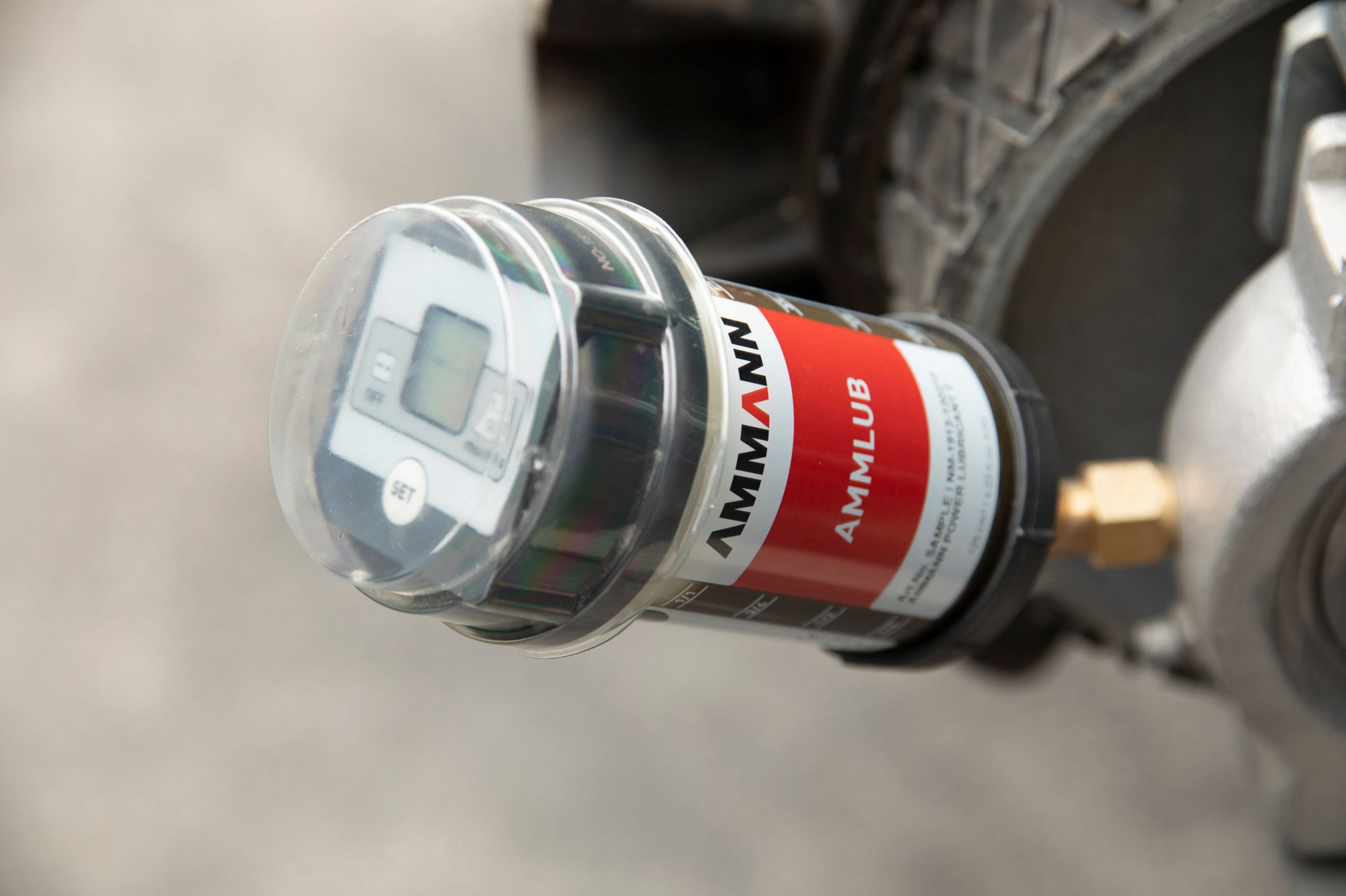
The Ammlub device from Ammann Group is mounted directly on the plant’s lubrication points.

All asphalt production businesses want to minimize the cost of ownership. The lower those expenses, the more competitive asphalt prices can be—and the higher profits can go. Ammann’s efforts to reduce asphalt operating expenses include Ammlub, which is Ammann’s automatic lubrication system, designed to provide three key benefits: longer plant life, reduced fuel costs and improved safety.

Traditional lubrication methods can be a struggle. They often require that technicians stretch and strain to reach extremely tight spaces—and that they fight dust, dirt and heat in the process. There also is the question of when to grease and how much grease to apply.

The labor-saving Ammlub system is mounted directly on the plant’s lubrication points. It automatically applies lubricants at scheduled intervals, ensuring that the process is done on time—every time. In addition, Ammlub eliminates downtime.

Fix a Torn Conveyor Belt

The lubricant applications can occur while the plant is running, enabling completion of the routine maintenance without a drop in productivity.

An immediate benefit is fuel savings, which can be reduced as much as 10 percent when all parts and components are working harmoniously.

With appropriate lubrication, those parts and components will also last longer, providing further savings. Because this system also locks out contaminants, plant life is extended, too.

Workplace safety is improved as well. Technicians no longer need to lug tools and fluids with them to access difficult-to-reach service points. These service points typically include all components along the process flow, starting with the cold feeder and ending with the discharge shoot.

For more information on the Ammlub product, contact simone.franz@ammann.com or visit www.ammann.com.

2. Astec Walks You Through Silo Maintenance Service

Inside this silo, a large hole is forming directly above the ceramic tiles. Areas like these were found along the entire circumference of the silo. Photo courtesy of Astec Industries

The team at Astec saw the need to make silo inspections safer and developed the SiloBot inspection device—a robot that is placed inside a silo by a trained inspection technician who then stays safely outside of the silo while performing a thorough inspection of the silo interior. A SiloBot inspection takes less than two hours to fully inspect all silo welds. With regular inspections, you can perform preventative maintenance that extends silo life.

Astec Engineering recommends having full silo inspections performed every two years, minimum. For high production facilities and silos that are 10 years or older, it is recommended to inspect annually.

Four Steps for Cleaning Disc Springs

Astec offers a recurring inspection plan for every 1-2 years that will allow us to provide the customer with comparative data. This data will help customers forecast wear in their silos so that preventative maintenance can be performed, giving them the ability to avoid spending unnecessary funds on more severe failures. Inspections can still be given on a one-time basis, as well.

Along with non-destructive thickness measurements, the SiloBot inspection device also checks for missing ceramic tiles, weld seam separation, damage to liner sections, holes in silo walls, batcher gate issues and other issues resulting in acute wear inside the silo.

One technician travels with two SiloBot inspection devices, software, a winch and mount, tools required for SiloBot device maintenance, and a truck with a mounted scissor lift in the bed. Customers are not required to rent manlifts.

The technician inserts the SiloBot through the mouth of the silo using a winch that is mounted on top of the silo (used as a safety tether and connected to the bot at all times) and the scissor lift mounted in the back of the truck. The incredibly strong natural magnets in the wheels allow the bot to traverse over ceramic tiles and onto the silo wall.
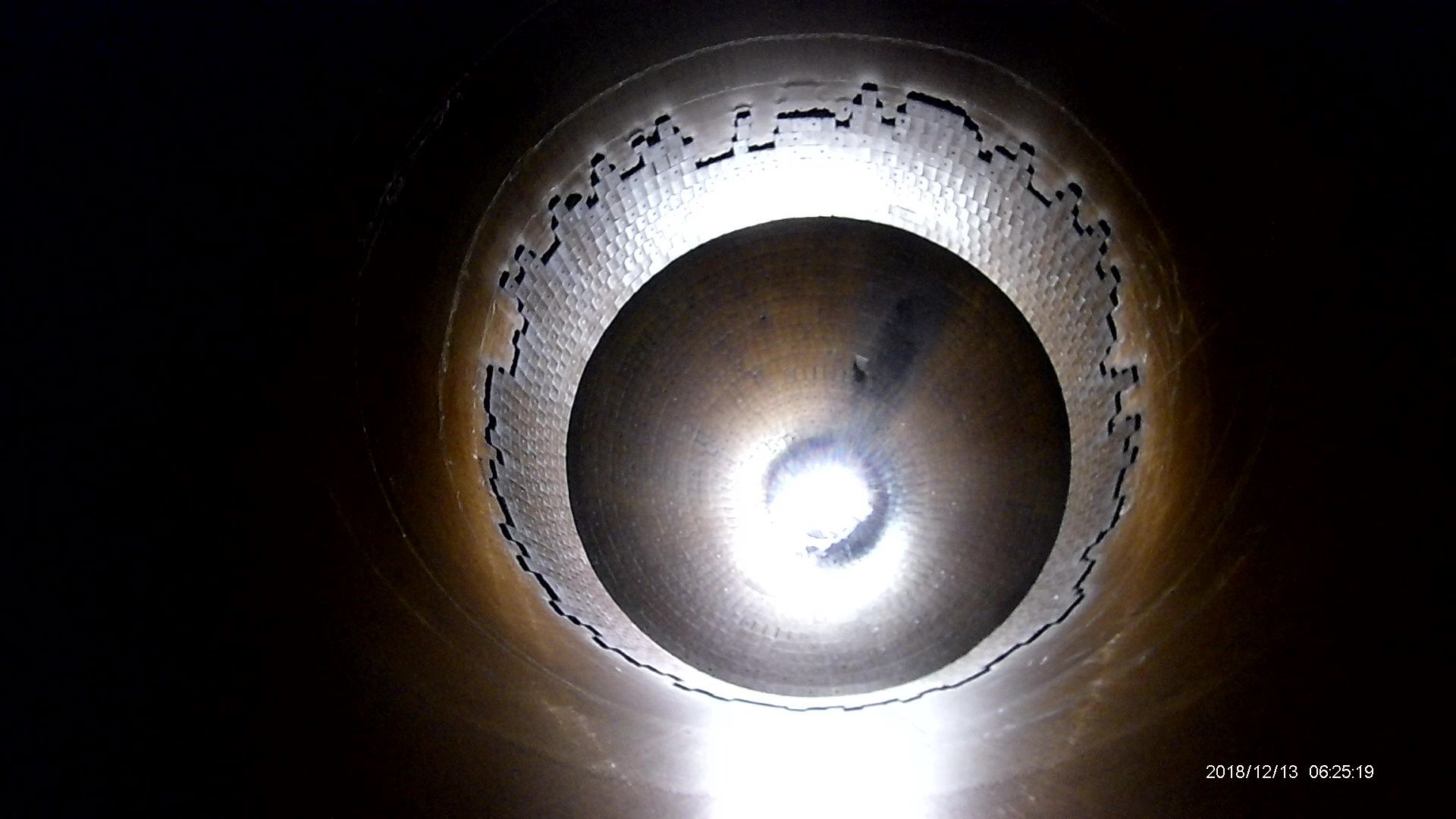
The large amount of missing ceramic tiles from the silo wall has allowed mix to wear the silo metal acutely in many areas. Multiple holes were found in this silo. Photo courtesy of Astec Industries

The SiloBot inspection device gathers data by utilizing a steel brush and motor to clean the silo wall prior to taking measurements with an ultrasonic thickness gauge. The data is then sent via a telemetry system linked to the technician’s laptop computer. This data is transmitted in real time, allowing the technician to view the results and fine tune the inspection as he goes.

Inspections range from 30 minutes to one hour, depending on the size and condition of the silo. The customer receives full 1080p HD video of each silo inspection on the day of inspection. The final report, delivered via e-mail in an average of 7-10 days, will include the raw data points, a graph that illustrates the location of these data points, and a written report with pictures that reference issues noted in the report. The report also features specific recommendations for repair.

SiloBot inspections can only be performed by a trained Astec technician due to the sophistication of the device and its components. Astec SiloBot Technician Alex Harrison said, “For customers with many plants, we devote ample time to get all of their inspections completed before moving to the next customer.”

If repairs are necessary, the repairs can be scheduled through the Astec Service Department or the customer can perform the repairs themselves.

To get information on the SiloBot inspection service, call on your regional Astec Parts or Capital Salesperson, or contact Alex Harrison directly at (423) 356-4791.

3. Brock Tells You When It’s Time to Change the Bags

While Nomex bags are most common for HMA plant operations, the industry veterans at BROCK recommend an analysis of the plant’s overall operation and mix designs to assess the right bag for the application.

There are a lot of factors that affect the life of a baghouse bag and factors will likely be different at each plant site. Bag material, operation temperature, gas stream content, dust size, air-to-cloth ratio, cleaning effectiveness and bag fit all contribute to how long bags might last and when it is time to change them out.

The team at BROCK recommends inspecting baghouse bags at least once per year, but preferably two to three times per year. We especially recommend checking bags as frequently as reasonable when the operation uses—or changes to using—diesel or heavy fuel oil in their drying process, as the lack of atomization in the burning process can lead to oil in the dust and, eventually, on the baghouse bags.

Things we advise to look for, bag wise, are change in bag color, visible changes to the outside texture of the bags, holes in the bags, and shrinkage in the bags. One key data point operators can use to measure the overall effectiveness of the baghouse, along with the bags themselves, is to measure the differential pressure in the baghouse. It can be a leading indicator of bag and/or dust system issues. Of course, dust coming out of the baghouse stack is the easiest to see with the human eye as a key indicator of bag issues.

Solve Asphalt Cement Tank Wear

There have been several bag types introduced to the industry over the last 30 years and the technology behind them has made great strides in that time in an effort to keep up with the changes in mix designs. Changes in mix designs include increased RAP percentages, stone matrix asphalt, open graded mixes, asphalt rubber, glass, roofing shingles (RAS) and warm mix, among others. These all affect plant operating temperatures, dust types and dust volumes the baghouse experiences.

Bags that are commonly found in today’s hot-mix asphalt production world include 14 oz. Nomex, Nomex singed, micro denier, hydro entangled, and P84, for higher temperature applications. Nomex singed is the bag we have seen that fits the most common needs of plants; however, we do recommend an analysis of the plant’s overall operation and mixes produced to assess the right bag for an individual plant.

For more information about plant assessments, contact Travis Sneed, vice president of sales and operations, BROCK, at tsneed@brock.industries or visit www.brock.industries.

4. Butler-Justice Shares Blue-Smoke Elimination
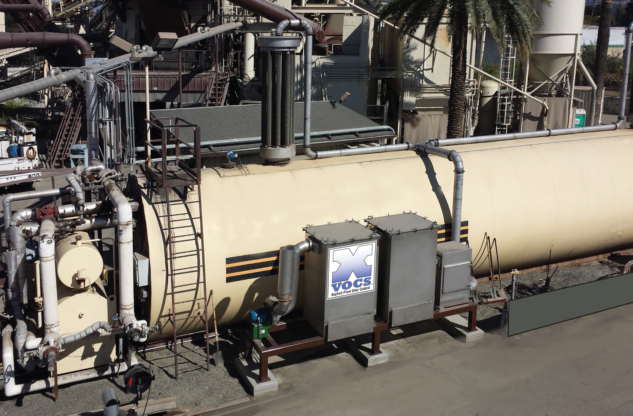
The X-VOCS system from Butler-Justice

As plants move toward the winter season, right now is an ideal time to assess any impacts from blue smoke and odors. Emissions from plants—both the classic, visible blue smoke and invisible volatile organic compounds (VOCs)—can cause challenges for producers, ranging from regulatory requirements to overt opposition from neighbors. Blue Smoke Control, a division of Butler-Justice Inc., Anaheim, California, offers two systems that, between them, is designed to eliminate both issues.

According to Mike Butler, president of Butler-Justice, “The addition of RAP, rubberized asphalt and polymer blends into asphalt mix designs has led to higher emissions due to higher mix temperatures.” His company now provides environmental control devices that can be installed at the asphalt plant to remove up to 99.9 percent of blue smoke, as well as the odors associated with asphalt production. Here’s how:

The Blue Smoke Control system captures blue smoke from emission points in the asphalt production process. Because blue smoke is essentially vaporized oil at high temperatures, Blue Smoke Control’s ducting system bleeds ambient (outside) air at key points. Seven stages of filters help to coalesce the tiny oil vapor droplets and aerosols into larger droplets that can be filtered out by the blue smoke collector. The oil droplets drain from the filters via gravity to a collecting sump.

Train New Operators to Unplug Screens

In addition, the company offers its X-VOCS system, which features proprietary carbon absorption technology designed to filter and remove up to 99 percent of odors and VOCs, such as Hydrogen Sulfide (H2S), from the hot asphalt storage tanks. The X-VOCS incorporates a five-stage filtration system. In the first three stages, a series of filters remove more than 95 percent of targeted particulates down to 0.3 microns. In the final two stages, carbon filtration beds remove remaining odors and volatiles.

When the X-VOCS technology is coupled with the Blue Smoke Control system, emissions from HMA plants can be reduced to nearly zero, providing owners with the means to achieve the highest level of environmental stewardship.

Implementation of this technology has been proven to virtually end calls from nearby neighbors regarding odor and visual emissions. Both the Blue Smoke Control and X-VOCS systems can be incorporated into new plant designs, and they are also easily retrofitted into existing plant operations, with minimal modifications to the plant.

For more information on the X-VOCS system, contact mikeb@butlerjustice.com or visit www.bluesmokecontrol.com.

5. CWMF Offers Tips to Care for Your RAP System
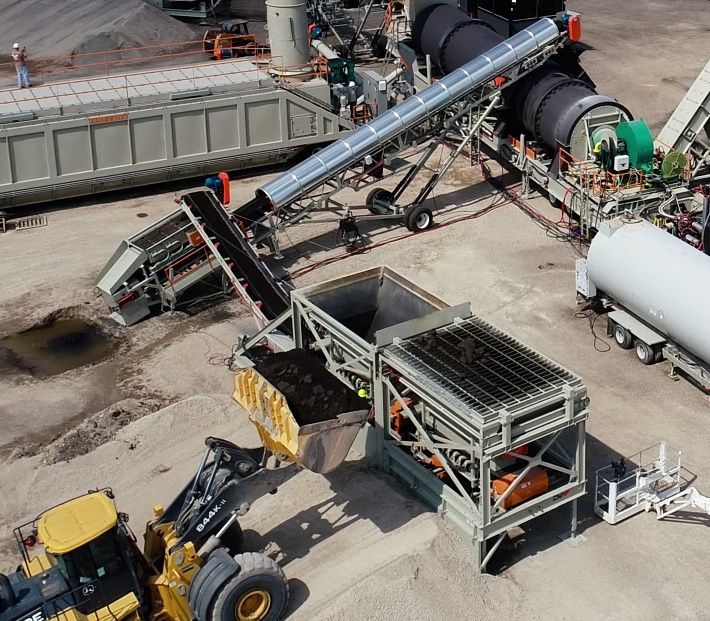
Make sure seasonal maintenance includes a close look at your RAP system. Photo courtesy of CWMF

You can take preventative measures during the winter season to ensure a smooth process in the spring. Being proactive saves money and headaches when it’s time to start back up. Executing a preventative maintenance schedule for your RAP System in the winter, can lead to smooth sailing in the spring. Maintenance looks different for everyone, so here are some generalized tips to help reduce problems when it’s time to start running again.

The main components of a RAP system consist of the bins, collector belt, Tremor Shaker, Honey Badger hammermill, and scale conveyor. As a reference, the team at CWMF suggests looking through your manufacturer’s manual for specific maintenance recommendations. Additionally, you can follow these tips to help create your maintenance schedule.

Start by checking the obvious. Are your belt idlers functioning properly? Inspect the belt scraper, checking to see if the blades need replacement and if they’re set at the proper tension. Check for any tears in the belt splices and determine whether they should be repaired or replaced. Inspect all flashed or sealed-in areas to see if they are worn or need to be replaced. Check the shape of the screen cloth. Is it worn? Does it need replacement?

How to Unclog the Asphalt Silo Safely

If you’re using a Honey Badger hammermill for oversized RAP, the consumables should be inspected, including hammers and liners. Look at wear life for both, and if replacement is needed. All drives should be checked for fluid levels in the reducers, and the shape of the v-belts. Make sure guards are intact.

The belt scale should be inspected and calibrated (go through the calibration process to verify proper function prior to startup). An accurate belt scale results in a quality mix.

Finally, check all electrical switches, i.e. limit switches and e-stop cable pulls for proper function.

This maintenance may seem small or tedious, but in the long run these are the things that tend to get overlooked, causing delays in the startup process resulting in costly downtime. Be sure to take time and follow your preventative maintenance schedule. Maintaining the proper functioning of your RAP system will help ensure your startup runs smooth like a freshly paved road.

For more information on the RAP system from CWMF, contact Travis Mick at sales@cwmfcorp.com or visit www.cwmfcorp.com.

6. Gencor Makes You an Energy Star

As Dennis Hunt, vice president of Gencor Industries, Orlando, Florida, often says with regard to anticipated performance of a hot mix asphalt (HMA) plant in response to design and operational changes, “it depends.” This very much applies to plant energy efficiency and fuel consumption. Per Hunt, there are numerous operating variables affecting energy efficiency and fuel consumption. These include: moisture content of the virgin and recycle feed stocks, counter-flow dryer virgin material veiling pattern, main exhaust temperature (waste heat), and use of warm-mix systems. While Gencor Industries works with its customers to optimize system performance, ultimately it is the responsibility of the end-user to run the plant in an energy-efficient manner.

One energy-efficiency measure that can, and is, integrated into HMA plants by the original equipment manufacturer (OEM) is insulation. Baghouses are insulated to prevent undesirable water condensation. Storage silos are insulated to keep the product mix at the required load-out temperature. Jacketed asphaltic cement piping can—and should—be insulated for both energy efficiency and worker safety purposes.

Another piece of equipment where insulation has become the norm rather than the exception is the counter-flow dryer.

The shell temperature of an uninsulated counter-flow dryer will range anywhere from less than 300⁰F at the ends (virgin aggregate feed breeching, and mix discharge to the finished product, or slat, conveyor) to perhaps more than 600⁰F in proximity to the combustion zone. Convective and radiant heat loss from an un-insulated dryer shell can be significant.

Solve Blue Smoke from High RAP

Insulation on a typical Gencor Industries counter-flow dryer covers approximately 75 percent of the surface area of the drum. The temperature of the insulation skin on a counter-flow drum will be in the range of 100 to 150⁰F. A substantial reduction in temperature that translates into, not only improved worker safety, but reduced energy requirements. A rule-of-thumb historically employed by Gencor is that insulating a dryer will reduce energy requirements by approximately 3 to 8 percent. Actual improvement in energy efficiency and associated payback period of the investment in insulation, of course, “depends.”

For more information, visit www.gencor.com or theasphaltpro.com/articles/how-to-be-an-energy-star/.

7. Haver & Boeker Helps Analyze Vibrations

Pulse vibration analysis technology can be used to evaluate vibrating screen performance. The team at Haver & Boecker Niagara, St. Catharines, Ontario, now partners with maintenance managers and plant managers to analyze screening processes, helping them meet production goals and overcome challenges with its Pulse Vibration Analysis Service.

Wilm Schulz, Haver & Boecker Niagara’s parts and service manager, explained: “Our Pulse Vibration Analysis Service offers more than just technology. We want to help our customers by serving as an extension of their maintenance teams, bringing the knowledge of an OEM to help support their operation.”

Lock Out/Tag Out For Safe Plant Maintenance

The service uses the company’s Pulse Vibration Analysis software to examine the health of a vibrating screen. Pulse detects irregularities that could translate into diminished performance, decreased efficiency, increased operating costs and imminent breakdown. This gives producers advanced notice so that their operation can plan preventative maintenance programs to avoid premature wear, downtime and additional expense.

The service program includes a complete vibrating screen inspection by a Haver & Boecker Niagara certified service technician. Following the inspection, customers receive a Pulse Diagnostic Report, which provides an analysis of their vibrating screen and detailed recommendations to prevent downtime. All Pulse Diagnostic Reports are stored in an online asset management system, giving customers access to a complete record of their vibrating screens’ service and performance histories.

For more information about Haver & Boecker Niagara’s Pulse Vibration Analysis Service Program, contact Kristen Randall at k.randall@haverniagara.ca or visit www.haverniagara.ca.

8. Kenco Advises for Longer Component Wear Life
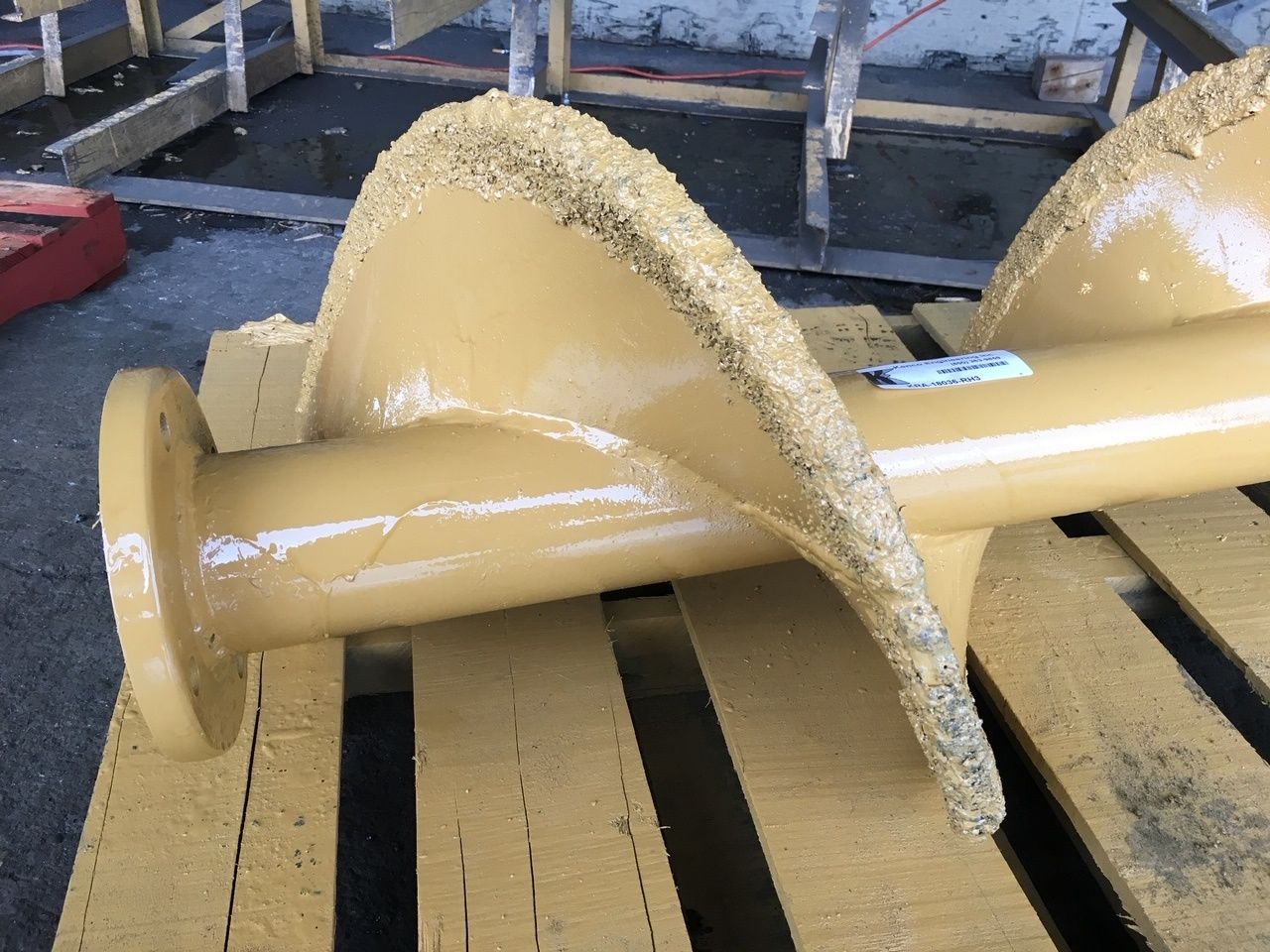
This photo shows the Kenco Engineering TCI steel strips installed on an auger.

Kenco Engineering Inc., Roseville, California, has been working to extend the life of augers for decades. At first, we developed the cast, bolt-on, auger shoe. This shoe incorporated a “lip” that wrapped over the outer edge of the auger to prevent the most common type of auger wear—diameter shrinkage.

In many cases, an auger running in an abrasive material will wear from the outer edge toward the shaft, thus reducing the diameter of the auger, more than on the face of the auger. This diameter shrinkage dramatically reduces efficiency of the auger and its ability to transfer material.

Over the last few years, however, we have learned that using our Tungsten Carbide Impregnation (TCI) process to protect augers can perform even better than the cast shoe around asphalt plants, especially the dust fines reject auger.
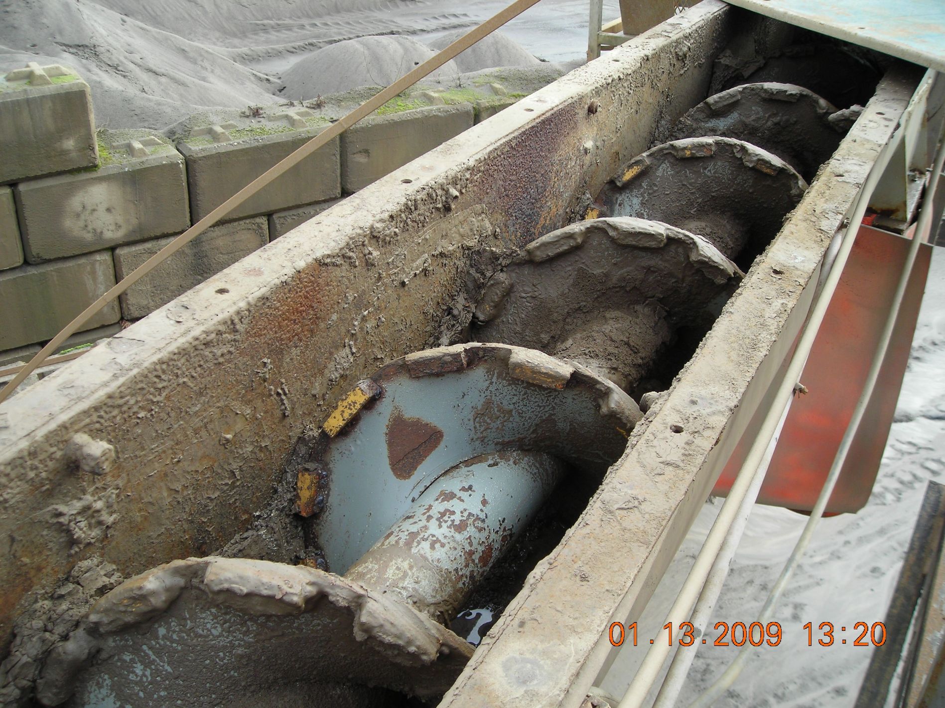
This photo shows a fines reject auger that, for many years, had averaged losing 1 inch of diameter per month. This photo was taken at five years of service with no loss of diameter during that period.
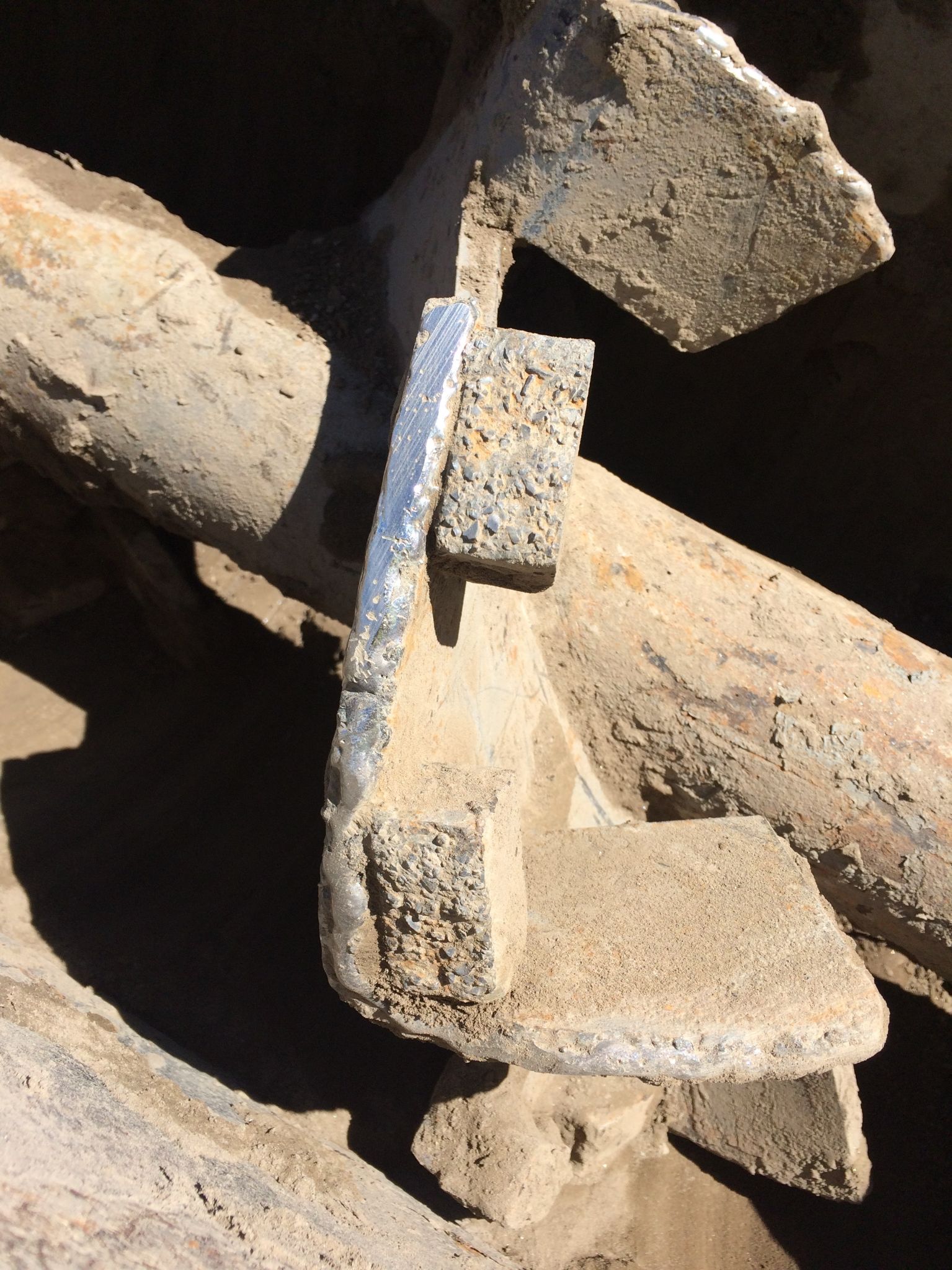
This next photo shows the use of our TCI bars on a “cut and folded” style dust auger. This customer had been changing out this auger half-way through each season. This photo was taken in the third season and the auger is still going strong.

The exceptional wear life of our TCI products comes from multiple factors. First is the hardness. At 90 Rockwell A, the hardness of Tungsten Carbide inherently makes it more wear resistant than even the hardest of AR steels. Next, with the rough texture of our TCI product, it traps material and helps create the cheapest of all wear products, material on material.

The versatility of our TCI product also enhances its usefulness around an asphalt plant. These two photos show the use of wear strips where Kenco impregnates our TCI into mild steel strips. These strips are then cut to size by the plant mechanic for installation on the auger or anywhere else wear is an issue. Due to their mild steel base, these strips can be welded with most common wire or electrodes for easy installation. As a final option, Kenco can manufacture a completely new auger with TCI protecting the outer radius as well as some portion of the face.

For more information on TCI protection, contact Brian Handshoe at brian@kencoengineering.com or visit www.kencoengineering.com.

9. Stansteel Tracks Your Trunnion Adjustment
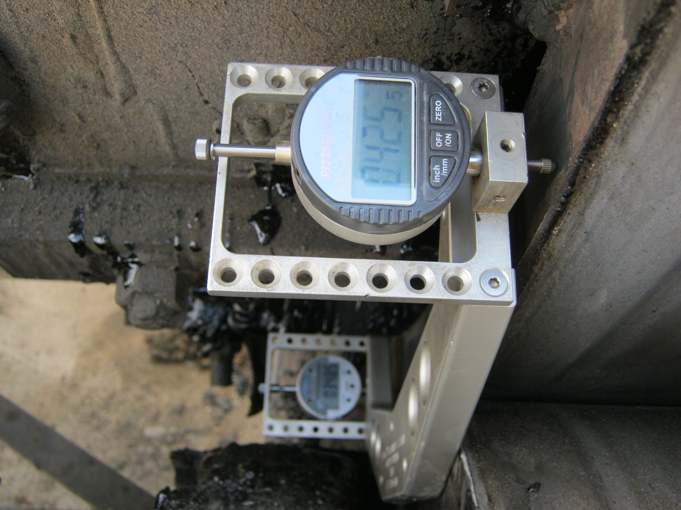
Depending on what stage of the adjustment process you’re in, you may want to see the numbers on the front and back displays be the same so the drum is not running uphill or downhill. Photo courtesy of Stansteel/Hotmix Parts & Service

Correctly adjusted trunnions reduce maintenance cost and plant downtime. Incorrectly adjusted trunnions cause a significant amount of abnormal wear and a multitude of premature failures that include broken thrust rollers, uneven tires and trunnions, and failed bearings. Precision adjusted trunnions maintain the plant’s tires and trunnions throughout the life of the drum and/or dryer.

There are many methods to adjusting trunnions. One common method is the use of a laser level and tape measure or other measuring device. This method is simple but not precise. While the laser beam is accurate, the width of the laser beam is not. Another attempt to keep trunnions properly aligned and skewed is to provide a measuring display on each trunnion base, but even this is not precise enough to prevent failures. The most precise and efficient method we’ve found for adjusting trunnions is our T-Trac Trunnion Alignment Tool by Stansteel and Hotmix Parts & Service. The T-Trac allows you to square the trunnions and tires within 100/1000th of an inch in precision.

In order to use the T-Trac correctly, lockout procedures need to be observed while working in contact with the equipment.

Once locked out and guards removed, the sides of the trunnions and tires need to be cleaned from dirt and grease.

The T-Trac consists of a magnetic base with dial indicators attached on each end facing the tire. Calibrate the dial indicators to the base with the included calibration blocks and the T-Trac is ready for use. Place the T-Trac on the side of the trunnion with both dial indicators on the side of the tire. Each of the four trunnions must be adjusted to the neutral position, meaning there is no longer uphill- or downhill-thrust. Adjust the trunnions to achieve a neutral (zero) delta between the two indicators, meaning that the trunnion is perfectly parallel with the tire.

The same method is performed for all four trunnions. Once all four trunnions are in a neutral thrust, the T-Trac can be used to skew each trunnion for the correct skew and thrust.

The trunnion adjustment methods of using a laser can take up to four to five hours to properly adjust your system. When using the T-Trac, precisely adjusting trunnions and tires can take as little as an hour and a half to complete the process for all four trunnions. The Stansteel & Hotmix Parts service technicians can visit your plant and demonstrate the T-Trac and adjust and skew your trunnions for you, ensuring precision accuracy of the adjustments.

For more information, visit stansteel.com.

Butler-Justice Inc.’s Blue Smoke Control System

Blue Smoke Control, a division of Butler-Justice Inc., Anaheim, California, offers two systems that, between them, are designed to eliminate emissions issues at the plant. According to Mike Butler, president of Butler-Justice, “The addition of RAP, rubberized asphalt and polymer blends into asphalt mix designs has led to higher emissions due to higher mix temperatures.” His company now provides environmental control devices that can be installed at the asphalt plant to remove up to 99.9 percent of blue smoke, as well as the odors associated with asphalt production. Here’s how:

The Blue Smoke Control system captures blue smoke from emission points in the asphalt production process.

Because blue smoke is essentially vaporized oil at high temperatures, Blue Smoke Control’s ducting system bleeds ambient (outside) air at key points. Seven stages of filters help to coalesce the tiny oil vapor droplets and aerosols into larger droplets that can be filtered out by the blue smoke collector. The oil droplets drain from the filters via gravity to a collecting sump.

In some cases, the system can pull as much as five gallons of oil per day from conveyor transfer points, silo-filling spots, and truck load-out areas. Not only is the final high-efficiency filter 95 percent efficient at capturing particles as small as 0.3 microns (creating a filter that is equivalent to HEPA quality), the complete system is 99.9 percent efficient overall, according to the manufacturer.

In addition, the company offers its X-VOCS system, which features proprietary carbon absorption technology designed to filter and remove up to 99 percent of odors and VOCs, such as Hydrogen Sulfide (H2S), from the hot asphalt storage tanks. The X-VOCS incorporates a five-stage filtration system. In the first three stages, a series of filters remove more than 95 percent of targeted particulates down to 0.3 microns. In the final two stages, carbon filtration beds remove remaining odors and volatiles.

When the X-VOCS technology is coupled with the Blue Smoke Control system, emissions from HMA plants can be reduced to nearly zero, providing owners with the means to achieve the highest level of environmental stewardship. Implementation of this technology has been proven to virtually end calls from nearby neighbors regarding odor and visual emissions. Both the Blue Smoke Control and X-VOCS systems can be incorporated into new plant designs, and they are also easily retrofitted into existing plant operations, with minimal modifications to the plant.

For more information on the X-VOCS system, visit the Blue Smoke Controls website.

How to Install and Use the Fiber Feeder (In 5 Steps)

Given the number of mix designs that call for cellulose (and other) fibers and other additions these days, producers may find themselves in need of a fiber feeder for a single project or for multiple projects coming up over a couple of seasons. Whether you need to rent a feeder or install one more “permanently,” the steps for setting it up will be similar. Let’s look at how to best install a block fiber feeder for the continuous mix plant and the batch plant.

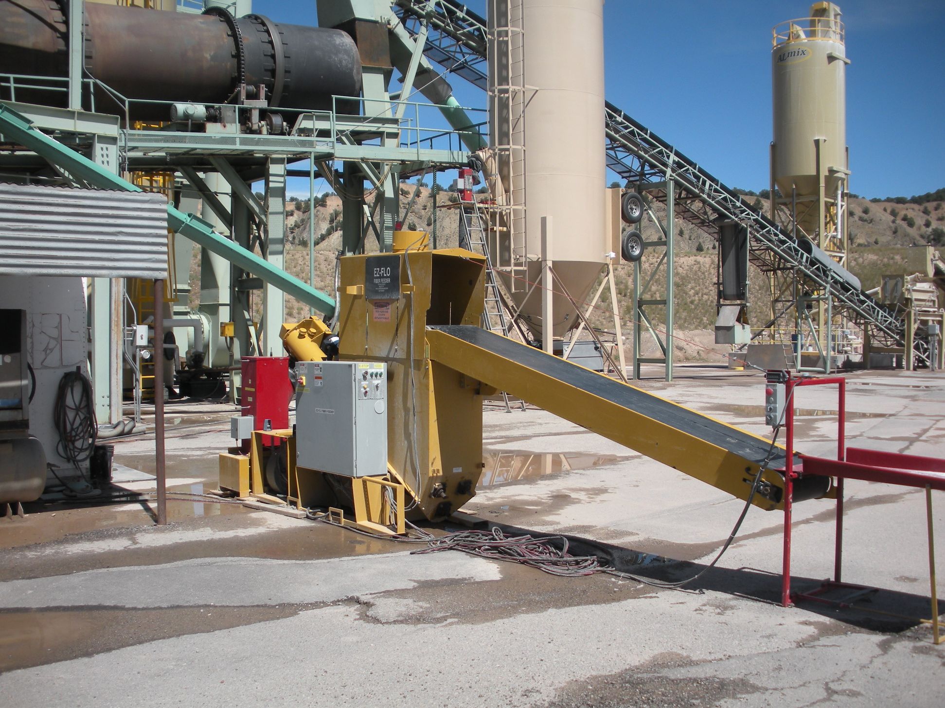
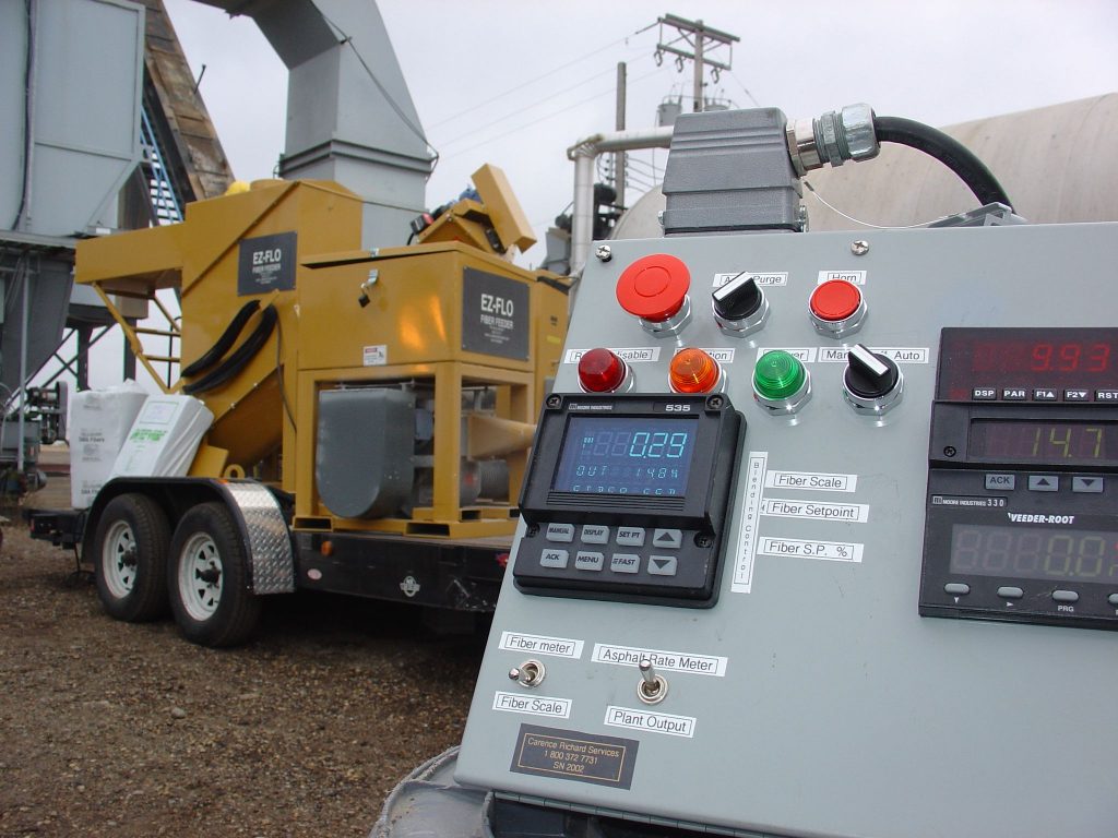
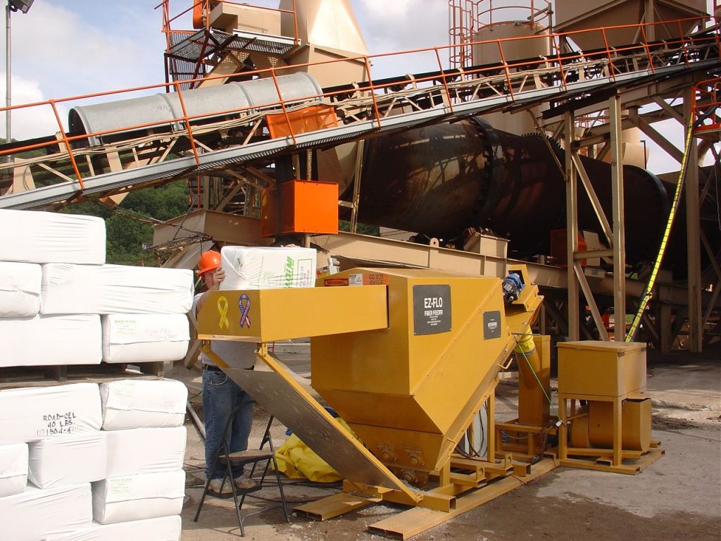
For fibers that are delivered in 44-pound blocks, use a feeder that conveys the blocks at a consistent rate to a weigh meter. As an example, the Ez-Flo Gen II feeder system, which Clarence Richard Services rents and sells, comes with 50 feet of 4-inch hose that couples to the mixer and with 200 feet of control cable that connects the feeder to the remote control. The remote control will be placed in the plant’s control room. The hopper and blower are mounted on a skid with a footprint of approximately 18 feet by 6 feet when lined up for production.

The remote control will be placed in the plant’s control room or, the control panel can be placed outdoors near the operation.

Step 1

Step one is to remove the skid from the lowboy and place it within a few feet of the mixing drum for ease of use.

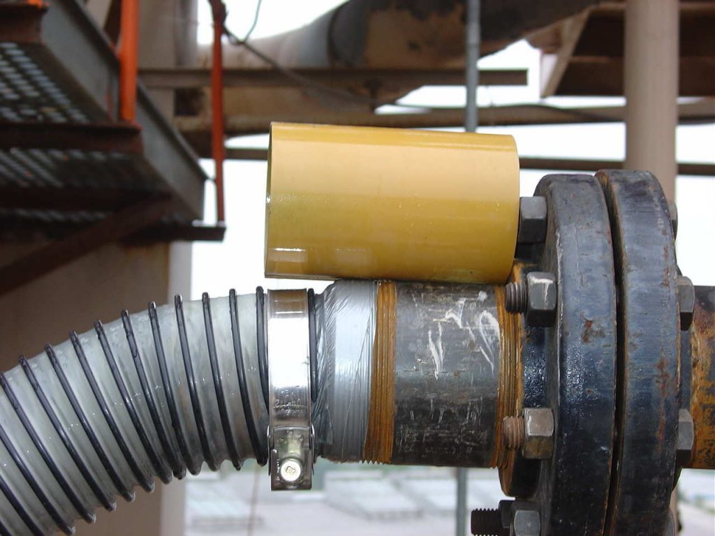
A 4-inch pipe is usually inserted into the drum, running below the dust auger or dust blow pipe. Sometimes, you can build a box around the AC-fiber discharge junction to ensure fiber doesn’t become entrained in the exhaust air stream. The connection show here illustrates what it takes to connect the 4-inch hose and pipe to each other. The insert is taped to the pipe and the hose then slips over the insert. The hose clamp keeps the hose connected to the pipe. This is a low pressure application; therefore, the tape will do a good job.

Step 2

Step two is to shim the underside of the skids to stabilize and adjust for any required leveling.

Notice the tarp covers the hopper to keep rain out of this process. Wet fiber is nearly impossible to work with. It’s difficult to break open the tightly bound fibers or to open them from one another.

Step 3

Step three is to set up the remote control panel, which may be located in the plant’s control house for the operator’s convenience.

Notice the tarp covers the hopper to keep rain out of this process. Wet fiber is nearly impossible to work with. It’s difficult to break open the tightly bound fibers or to open them from one another.

Step 4

Step four is to connect the control cable from the feeder to the remote control.

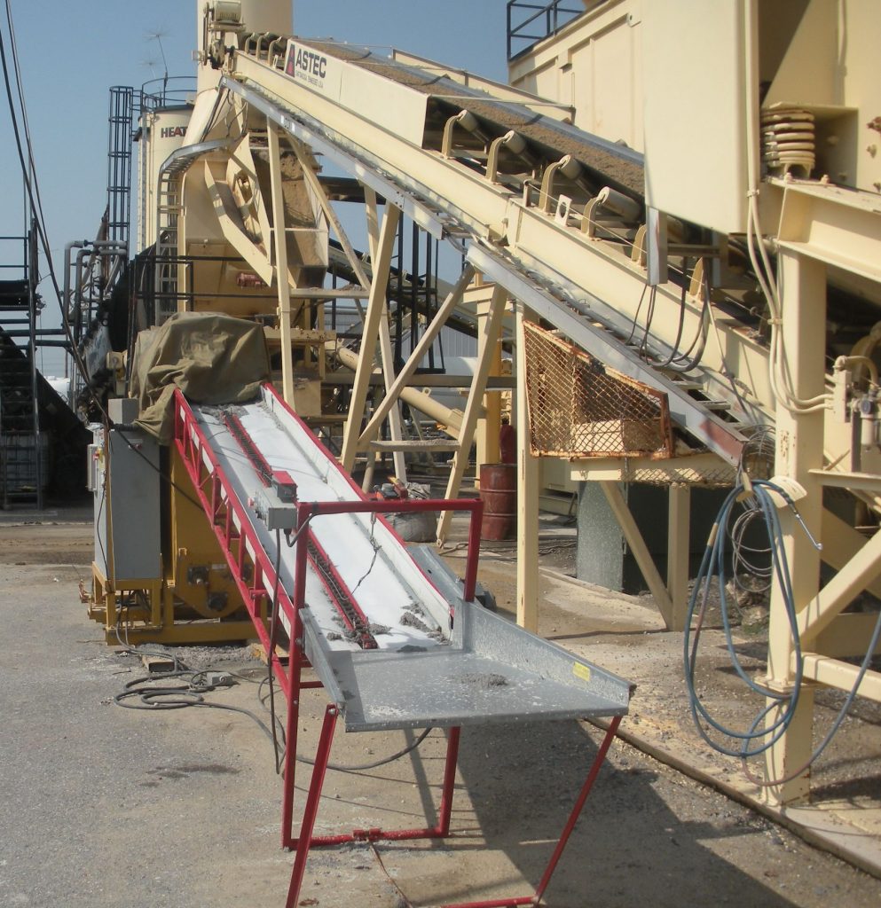
The ground personnel will place the bales of fiber on the conveyor, placing them end-to-end. You want to fill the conveyor with the bales; the conveyor will feed them into the hopper.

Step 5

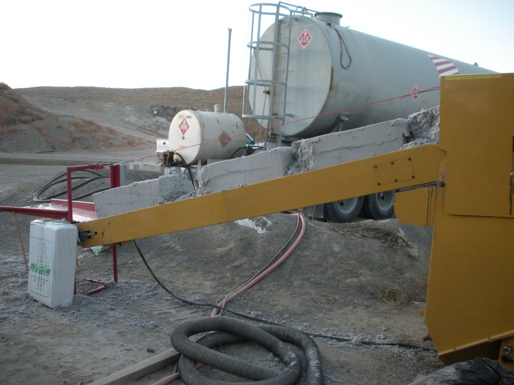
Step five, at the skid, is to pull the conveyor out from the hopper and fold out the table-conveyor support.

The ground personnel will place the bales of fiber on the conveyor, placing them end-to-end. You want to fill the conveyor with the bales; the conveyor will feed them into the hopper.

Ready to Go!

When ready to operate, the ground personnel will begin placing the bales of cellulose (or other) fiber on the conveyor. Place them end-to-end. Fill the conveyor with the bales, which the conveyor will send to its hopper’s augers.

The augers break up each bale into cottage cheese-sized chunks of fiber and feed it to the variable speed scale feed auger.
Fiber then passes through the scale into the air stream on the suction side of the blower.

FORTA’s Surface-EXT Fiber & Ranger Feeder

The blower conveys the material and opens the fiber chunks, separating the fibers from each other for maximum AC absorption. The fibers “meet up” with the liquid AC in the drum, usually at the point where the AC is being sprayed.

The scale reports to the remote control. When the plant rate changes, the fiber rate will also change—this proportioning is controlled by the set point.


Clarence Richard is the proprietor of Clarence Richard Services (CRS), Minnetonka, Minnesota. For more information, contact him at (800) 372-7731 or Clarence@clarencerichard.com.

Conveyor Safety Best Practices Prevent Accidents

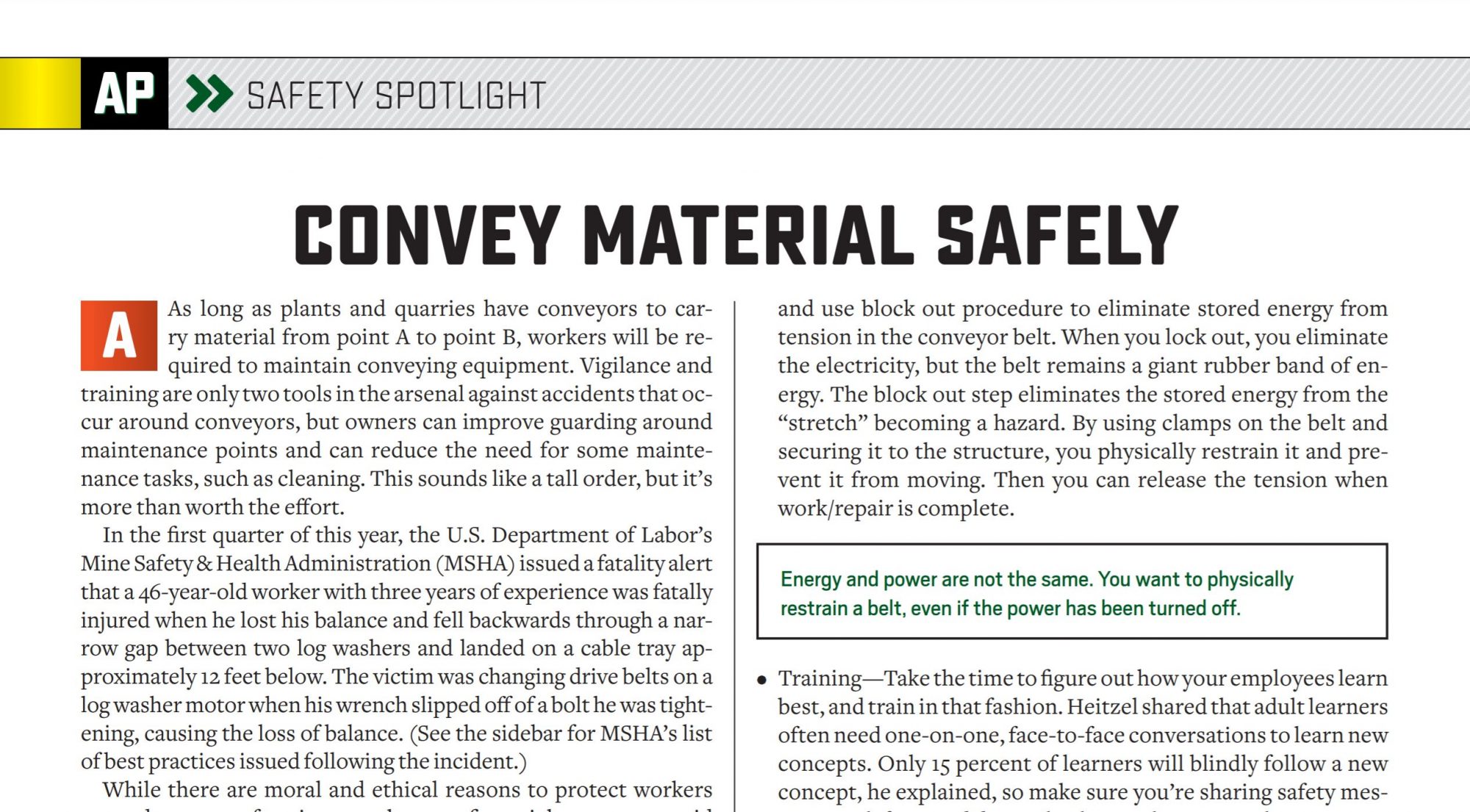
As long as plants and quarries have conveyors to carry material from point A to point B, workers will be required to maintain conveying equipment. Vigilance and training are only two tools in the arsenal against accidents that occur around conveyors, but owners can improve guarding around maintenance points and can reduce the need for some maintenance tasks, such as cleaning. This sounds like a tall order, but it’s more than worth the effort.

In the first quarter of this year, the U.S. Department of Labor’s Mine Safety & Health Administration (MSHA) issued a fatality alert that a 46-year-old worker with three years of experience was fatally injured when he lost his balance and fell backwards through a narrow gap between two log washers and landed on a cable tray approximately 12 feet below. The victim was changing drive belts on a log washer motor when his wrench slipped off of a bolt he was tightening, causing the loss of balance. (See the sidebar for MSHA’s list of best practices issued following the incident.)

While there are moral and ethical reasons to protect workers around any type of equipment, there are financial reasons to avoid injury for individual companies and the industry overall. During a conveyor safety webinar sponsored by Martin Engineering of Neponset, Illinois, Jerad Heitzler shared some hard truths.

Lock Out/Tag Out For Safe Plant Maintenance

“Whenever we have a conveyor accident, we have the risk of changing regulations for guarding conveyors,” he explained. “We see increased citations. We see increased attention from governing bodies. We see increased documentation. We see upgrades to lockout/tagout enforcement. We see upgrades to training plans. And we see lowered employee retention and morale. When we subject employees to accidents, it’s difficult to attract and keep skilled workers.”
Heitzler shared the story of a worker whose arm was broken in a pinch point while cleaning a conveyor belt. The workers’ peers went to visit the injured employee in the hospital and the scene was like a company meeting but “with an overwhelming feeling of dread.”

Companies combat such horror with a robust safety culture, and with top safety tactics that include a clean work site.

Energy and power are not the same. You want to physically restrain a belt, even if the power has been turned off.

Best Practice Tactics

Heitzler listed four main areas of best practices when working around conveyors, belts, rollers and return conveyors, etc., that we’ll discuss here.

  • Proper PPE—While the company is responsible for providing personal protective equipment, each employee is responsible for using it. When working around conveying equipment, employees can’t wear baggy clothing or jewelry. Long hair should be confined.
  • Policies, Procedures & Protocol—While the company must have policies in place, it is up to each employee to use procedures correctly. It’s wise to enforce more than lockout/tagout. Heitzler listed: Lock it out; tag it out; use test out procedure; and use block out procedure to eliminate stored energy from tension in the conveyor belt. When you lock out, you eliminate the electricity, but the belt remains a giant rubber band of energy. The block out step eliminates the stored energy from the “stretch” becoming a hazard. By using clamps on the belt and securing it to the structure, you physically restrain it and prevent it from moving. Then you can release the tension when work/repair is complete.
  • Training—Take the time to figure out how your employees learn best, and train in that fashion. Heitzel shared that adult learners often need one-on-one, face-to-face conversations to learn new concepts. Only 15 percent of learners will blindly follow a new concept, he explained, so make sure you’re sharing safety messages with facts and data to back up “why” your policies, procedures and protocol are vital.
  • Safety Equipment—When training safety concepts, the proper use of safety equipment is vital as well. For example, emergency stop switches can’t be used as the only line of defense at the conveyor belt. The emergency stop switch needs to be tested for slack (you want no more than 12 inches of slack, Heitzel shared) in its cable. The cable de-energizes the conveyor, but the conveyor continues to move until the cable runs out when the switch is tripped. Do your employees understand that hitting the switch doesn’t bring about an immediate stop? When testing the switch, measure, record and report the runout. Inspect the cables and clamps. Inspect the length and location of the stop.

Other safety equipment that can save a life is the guard. The guard around conveyors should have no sharp edges and should have no pinch point at the hinge. You want the guard to be removed only with a tool to access the belt for maintenance. It has to stand out in color from the equipment it’s “guarding” and it must be a proper distance from the hazard, opening or rotating piece of equipment. Heitzel reminded the audience to test the guard with the acronym A.U.T.O. You should not be able to reach: around, under, through or over a guard.

Keep it Clean

Eliminate the hazard by eliminating the need to climb onto equipment for cleaning. Heitzel shared the story of a worker simply sweeping the floor around an elevated conveyor component. The worker slipped and fell 60 feet to his death. Another terrible fact is that workers shoveling fines have had shovels get stuck in pinch points; before anyone could hit a stop switch, the force pulled the workers to a horrible end. Our industry must adhere to dust mitigation rules and regs, so reducing these accidents begins with reducing the need for cleanup. As an industry, we can do a better job of keeping dust from piling up. Heitzel suggested aggregate managers look into the following areas where technologies exist.

  • Reduce carryback
  • Install proper belt cleaning
  • Reduce dust around the belt
  • Use skirting, but don’t over-rely on it alone
  • Reduce belt sag with proper support
  • Maintain wear liners

It’s possible to mechanically control dust to prevent build-up. By limiting dust, we can reduce the opportunities for maintenance and cleaning-related accidents around conveyors.

How to Change Drum Flights

Editor’s Note: In this training column, AsphaltPro helps asphalt companies teach new workers back-to-basics techniques for best success in the field, at the plant and in the lab. Even veteran employees will be reminded of best practices with these refreshers throughout the year, but the goal is to help readers who are bringing in new employees who may or may not be well-versed in the industry yet. On-the-job training takes time and energy, and we’re here to help with the Asphalt Paving 101 online training course and these free articles in each issue.

Look Before You Flight

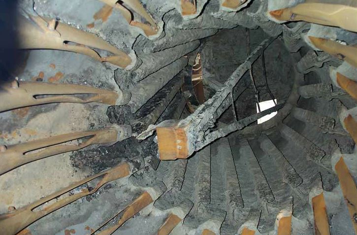
In all likelihood, over 95 percent of the dryers and drum mixers on hot-mix asphalt (HMA) plants no longer have the flights installed as built from the factory. Even if you have factory drawings, it is quite likely there have been either some or significant flight changes over the years.

Too often, producers have removed all the old flights before changing. With this in mind, we highly recommend a comprehensive survey of the exact flights in the rotary unit—number, quantity, positioning, etc.

This can be done by measuring and taking photographs in advance. Perhaps as important, if the dryer/drum is operating properly, there should be an actual performance analysis of the unit. A quick way to do this performance analysis is to run at the maximum tons per hour and use instrumentation to take two sets of readings.

The first set of readings will be to measure the shell temperature with an infrared gun at approximately every 3 feet along the length of the shell as the dryer is operating at maximum TPH, and at the turn-down or lower TPH rate. This will show how the unit is operating and if it is still operating in a satisfactory mode.

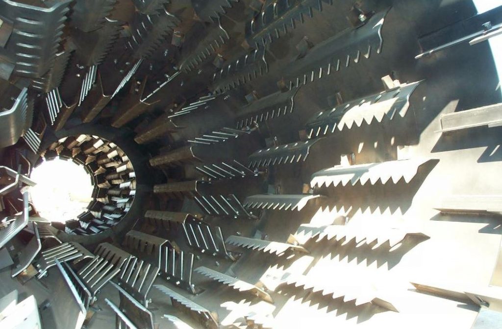
Before a complete flight change

Before a complete flight change

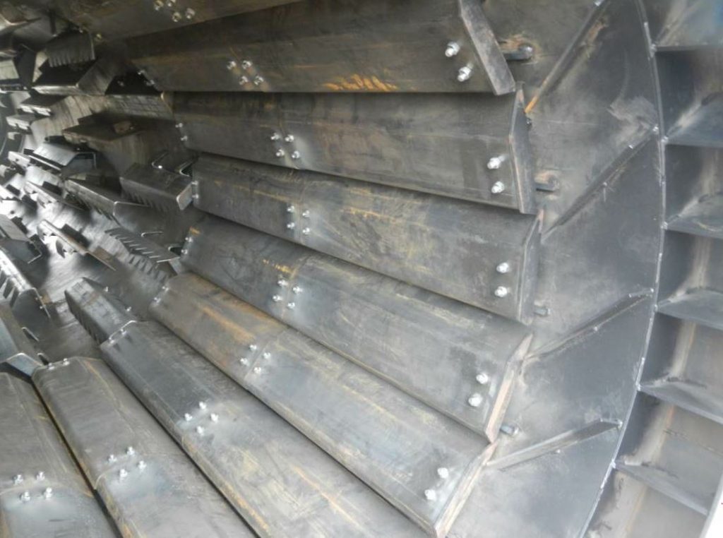
When the job is done

When the job is done

The second set of tests will be to have ports installed in the outlet duct from the dryer to the pollution-control equipment. On this outlet duct, approximately every 8 to 10 inches, take a measurement of the hot gas stream temperature. This, again, will indicate the efficiency and if there is proper veiling by comparing the profile of temperatures from one side of the unit to the other.

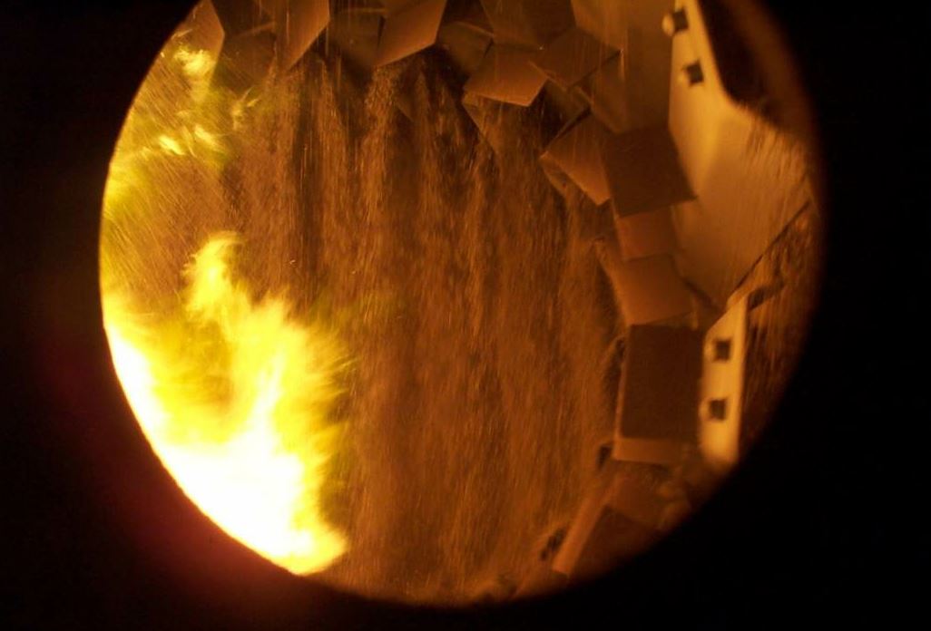
Flighting in an HMA dryer or drum mixer serves multiple purposes such as promoting heat transfer and combining the different materials for mix. A proper flighting system in good repair controls the flow of material and protects the rotary shell. When flights have worn or you need to effect a new/different dwell time in the drum, you’ll change any number or type of flights.

It’s the plant manager’s—or the equipment manager’s—responsibility to determine the proper flight patterns to achieve designed flow effects. This article is focused not on the purposes of different flights, but on the proper procedure for replacing them.

In the foreground, you see new combustion flights installed for production.

In the foreground, you see new combustion flights installed for production.

Safety in the Dryer

First and foremost, be safe. All service operations at the asphalt plant require a basic group of personal protective equipment (PPE). That group is as follows:

  • Hard hat
  • Safety glasses
  • Personal fall arrest protection
  • Face shield
  • Hearing protection
  • Long sleeve shirt
  • Gloves (leather, cut-resistant)
  • Steel-toed shoes (all leather upper); 8” boots are recommended

As needed, PPE will depend on the work environment and may include:

  • Respirator
  • Welding respirator with PAPR or supplied air
  • Flame resistant clothing
  • Tyvek™ coveralls
  • Boots with metatarsal coverage

The very first thing ground personnel will do is lock out and tag out the drying unit’s power source. Then lock down the drying unit by use of come-a-longs or tuggers. Also use wooden chocks—place these in the pinch points of tires and support rollers to further ensure the drum can’t accidentally move.

Another caution: It is not recommended to attempt to change one row of flights at a time. There can be many problems of interference from other flights and it’s hard to get the entire arrangement positioned correctly. Even though sometimes people want to, on a weekend day, change one or two rows, if the entire unit is going to be re-flighted, it is far preferable to do it all at one time.

Did you obtain a confined space permit and the proper monitoring equipment? You will assign a confined space attendant to keep watch over the worker(s) from outside the drum. The confined space attendant, continuous monitoring, proper PPE and ventilation at four times the volume of the unit are all required during maintenance activities. Depending on the method of replacement, the material of the unit or flights, or the material that has been present inside the unit, the workers may need respiratory protection equipment.

Replace Welded Flights

Step 1. Use an arc gouger to cut existing welds in the bottom quarter-section of the unit and remove flights.
Step 2. Clean and grind any residual welds left from the demo process.
Step 3. Lay out and install new flights in that section. (If installing a different style flight or different pattern, this shall be determined by a qualified source.)
Step 4. Remove chocks at pinch points and remove tiedowns.
Step 5. Rotate unit until next quarter-section is located at the bottom.
Step 6. Repeat steps one through five until complete.

Replace Bolted Flights

Step 1. Use an arc gouger or torch to cut bolts that hold the existing flights.
Step 2. If like and kind flights are to be installed, inspect the existing mounting brackets. Make repairs or replace the brackets before installing new flights in the first quarter-section located at the bottom of the unit.
Step 3. After installing new flights and bolts, weld the nuts to the bolts. Bolts should be installed with the head of the bolt to the product side of the flight.
Step 4. If changing the flight design or pattern, the new design or pattern shall be determined by a qualified supplier. This process may require removing the old mounting brackets and installing new ones.

Power Back Up

One of the best common sense tips is once the unit has been secured, cleared and the power restored to the drives, it is best to rotate the unit without any material. Listen for any items that might be loose, whether that’s flighting, attachments, seals or more. Once that is done, the best practice is to rotate the unit with aggregate material to make sure there is no bridging or plugging, also just to test and make sure all the flighting has been secured.

After that point, the best method is to start and run the operation under full load. Go back and measure with the infrared testing instrument to see if the shell temperature profile is the same or hopefully better than before. Finally, go to the exhaust duct and check the multiple ports for temperature readings to gauge efficiency and that proper veiling has a consistent temperature throughout the exhaust gas discharge.

Then run production for months or years and keep checking and maintaining temperature profiles.