CWMF Launches Portable, Stationary Recycled Asphalt Crushing Systems RAP Boss and RAP Boss Jr.

CWMF, St. Cloud, Minnesota, has launched the portable and stationary recycled asphalt crushing systems RAP Boss and RAP Boss Jr., building on the reclaimed asphalt pavement (RAP) equipment Honey Badger hammermill RAP crusher and Tremor Shaker™ scalping screen.

The difference between the RAP Boss and the RAP Boss Jr. is size, scale and price. Both are portable or stationary, efficient, and make the most of recycled asphalt for optimal sustainability, according to the manufacturer. This heavy-duty industrial equipment manufactured by CWMF is designed to process milled and recycled asphalt that mixes with liquid asphalt cement (AC) and other aggregates to make high-quality asphalt for paving.

The RAP Boss and RAP Boss Jr from CWMF are available in portable or stationary configurations and incorporate the Honey Badger hammermill RAP crusher and Tremor Shaker™ scalping screen.

“Our RAP Boss and RAP Boss Jr. recycled asphalt systems allow hot mix and crushed asphalt producers to minimize material handling, reduce or eliminate RAP crushing costs, and reduce RAP product moisture,” explained CWMF Sales Manager Wally Olson. “Sustainability and cost efficiency are important to everyone, and these new systems streamline the production process for both plant development and ongoing operations.”

For more information, visit https://cwmfcorp.com

Top Plant Fixes to Plan for Winter Downtime

Plant components providers offer more than iron in this industry. These companies often employ salesmen and engineers who have been in the trenches alongside plant managers, operators and groundmen for years. Their combined knowledge is something we wanted to tap into as we head into the 2023-24 winter season to help producers make their best plans for most efficient use of seasonal downtime.

Before you shut down for the winter, give your facility a thorough inspection. Take a temperature gun or thermal camera, digital camera, and a can of spray paint with you as you and your safety spotter go around to each of the areas the experts have listed in this article. You’ll want the temperature gun to measure hot spots where the iron is wearing thin and to double-check electric panels. Use the camera(s) to document issues and then spray paint to mark “items” for the maintenance crew to address. Even with today’s software and apps to assist in documentation, tracking, scheduling and so on, these old-fashioned best practices can save some time and angst when it comes to sharing information and getting repairs underway efficiently.

5 Steps for Asphalt Plant Silo Repair

Even with sources not included here, a common theme was to “look for wear.” Overall, the trend was toward shoring up what you already have in place—when possible. After reviewing some of the areas and componentry listed below, you’ll see the need to perform a second inspection after the plant is shut off and systems are locked out/tagged out for best safety considerations. Even those hard-to-access areas need to be checked so they aren’t offering an unwelcome surprise in the middle of operations in 2024. Here’s the advice of seasoned professionals for mapping out this year’s plant maintenance for best use of your time and money, and best season start-up next spring.

Take a temperature gun or thermal camera, digital camera, and a can of spray paint with you as you and your safety spotter perform a thorough inspection of the plant.


Experts Recommend

Travis Sneed, the vice president of sales and operations at BROCK, Chattanooga, Tennessee, recommended specific components to inspect, including the cold feed bins, drum, drag, silos, baghouse and electrical systems.

  • At the cold feeds, look for wear on the bin walls, conveyor belts and idlers.
  • At the drum, look for hot spots and wear. Also check the tires/trunnions for unusual wear.
  • At the drag, check the chain and sprockets for wear.
  • At the silos, look at the bottom gate and cone for wear. Check for bulging skin, which will be a sign of holes in the silo.
  • At the baghouse, look closely at the ductwork for any visible hot spots or signs of wear. You’ll also look for hot spots in the baghouse itself. Check the baghouse bags, too. Check the fan blade for wear.
  • With the electrical systems, make sure cables and connections are still in good condition. Inspect switchgear for any abnormalities such as evidence of water or heat exposure.

Steve Klein of Clarence Richard Company shared, “While there are many items to look at, I like to think of systems points that are commonly overlooked.” Klein listed drives, aggregate wear surfaces, plant fluids, plant air systems, and plant cords and wires as the top five areas he’d recommend the plant maintenance personnel walk up to and inspect. When using the thermal camera, point it at the electrical system.

“When one plant I was at first got a thermal camera, they looked at the switch gear, which made sense,” Klein shared. “Then as we looked at the control terminal strips [we] had a large surprise to find how well a loose terminal showed up. Since then, control wiring was added to the list to check with switch gear, gear boxes, top of the baghouse and the ductwork with the camera. Thermal camera surveys recorded make a great reference to show wear in many areas of the plant. It can even show liners getting thin, plugged hot oil lines and the like.”

Alternatives Exist to Source Asphalt Plant Parts

Klein breaks down the maintenance list with the following:

  • Drives—Check the wear on V belts with a gauge. Also look for physical wear and glazing. Also check the V belt sheaves for wear due to slippage. Check sprocket wear on the chain drives. On the chain, look at the barrels of the links for wear. Measure 10 or 15 links to determine inside link wear. Check the fluid condition and level of reducers. Also look at the condition of their power cords.
  • Aggregate Wear Surfaces—Here you’re looking at thickness. Look at the thickness of bins, feeders, chutes, hoppers, flights, drum shell, drag slats, silo batchers, discharge gates and cones.
  • Plant Fluids—Not only will you look at fluid levels, but also look at their general condition. Are fluids gritty or is there water in the oil? You’ll want to perform fluid testing; get samples and send them out for analysis.
  • Plant Air Systems—Is the ductwork in good condition or are there leaks or plugs of dust buildup? Send bag and dust samples for analysis to determine bag wear and expected life left to them. Check the seals in the drum for all aggregate inlet and outlet; also check dryer rotary seals.
  • Plant Cords and Wires—Look for cuts or worn-out spots in cord coverings. Also look at cord and wire placement. Are they out of traffic, off the ground and or otherwise not in danger of getting hooked by equipment? It may be time to shore up the support of sagging wires.

The team at Kenco Engineering Inc., Roseville, California, also spelled out some of the areas plant managers and ground personnel tend to overlook. They called attention to RAP entry chutes, virgin material entry chutes and distribution flop gates at the top of the silos as examples of areas often ignored until it’s too late.

Brian Handshoe, vice president of operations for Kenco, explained that in each case, the reason these areas get ignored is due to their difficulty of access. “Since they are hard to access, the typical scenario is that the plant manager will continue running the plant until a large enough hole occurs to force the plant to shut down production,” Handshoe said. “The holes that occur create plant inefficiencies as well as lead to accelerated wear that makes the hole larger and larger until addressed.”

The way this mid-season wear is typically addressed, he lamented, is with short-term patching of the worn area or hole. “The temporary fix will last until it doesn’t, and the whole process repeats itself.”

9 Tips for Asphalt Plant Maintenance

He shared that the amount of time you can get out of the temporary fix will depend on how many tons per day you put through the drum and how abrasive the aggregate is. Getting wear spots shored up properly during the maintenance season is the less-stressful scenario.

Kenco’s Jim Alexander also highlighted the discharge ring as an area to double-check. “After speaking with multiple plant managers, the most common area they forget to check is the discharge ring,” Alexander shared. “They installed tungsten carbide (TC) discharge flights and didn’t look at the drum ring. They now use pieces of TC wear bar to protect the ring. The drum ring was being replaced annually, now the TC bars are checked annually and replaced approximately every three years. Most areas improve 3 to 5 times with TC strips in place.”

Alexander shared that, “Flop gates can be critical if they get a hole that goes unnoticed, they get contaminated product or unknown filling of an assumed empty silo. Other areas were also a result of extending primary wear problems such as recycle collar, flop gates, and chute transition points.”

No matter how the wear problems are creeping into your operation, performing a set of thorough inspections to find them before and after shutdown is the first step in preventing unplanned downtime next season. Make sure the areas the experts have listed for you here are added to your inspection map.


To contact the experts who assisted with this information:

Travis Sneed at BROCK

Tsneed@brock.llc

(423) 476-9900

Steve Klein at Clarence Richard Company

Shklein56@gmail.com

(952) 939-6000

Brian Handshoe and Jim Alexander at Kenco

www.kencoengineering.com

(800) 363-9859


Saving Downtime at the Belts

The Model DB belt rip detector from Conveyor Components Company is designed to minimize conveyor belt damage when a tear or piercing foreign object affects the belt.

Those readers with quarry operations in addition to plant facilities may be interested in the Model DB belt rip detector, manufactured by Conveyor Components Company, which operates on a cable pull concept.

When a belt flap or tear—or a foreign obstruction such as a piece of rebar—has pierced a conveyor belt, the cable releases the activation ball from its protective socket and trips the device. The outputs of the Model DB can control up to four separate circuits, depending on the model chosen. These alarms can include one for machinery shutdown, which minimizes further conveyor belt damage, and one for alarm.

This standard housing construction is corrosion-resistant cast aluminum, with an optional polyester or black epoxy powder coating. The protective rubber boot on the cable assembly is designed to keep the activation mechanism clean.

For more information, contact Conveyor Components Company at (800) 233-3233.

Super Asphalt Expands Asphalt Production South

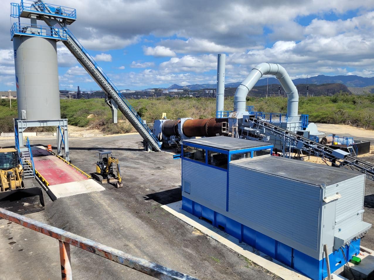
By combining used and new plant equipment, Super Asphalt has expanded its Puerto Rican asphalt production business to the southernmost part of the island.

Miguel Suria, Super Asphalt’s operation manager, has been with the company from the beginning in 1999. Under his guidance, the island-based asphalt producer has grown to seven plants in the past 23 years. Suria came to Super Asphalt with a wealth of plant knowledge and experience. Over the years, he has often recommended that Super Asphalt purchase gently used equipment to meet their needs. For this plant project, Reliable Asphalt Products had a plant that met Super Asphalt’s requirements.

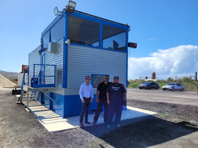
Miguel Suria is proud of the latest Super Asphalt plant. Photos courtesy of Reliable Asphalt Products

Mike Mauzy, co-owner of Reliable Asphalt Products, has worked with Super Asphalt in the past so he was familiar with their requirements. “As I was seeing customers, I had in the back of my mind the need for a plant to go to Puerto Rico. Once I saw this plant, I felt like Super Asphalt would like it too.”

The plant combined components from several manufacturers. It was equipped with a Cedarapids E-300 counterflow drum, a portable Madsen baghouse, a set of portable cold feed bins and a portable HyWay tank. The plant also had a silo system with more storage than Super Asphalt required.

Suria mentioned, “We didn’t need more than one silo, so we bought a new silo system instead of paying for the freight to move the system to Puerto Rico.”

Even though this plant was not complete, the components that were available met the needs of Super Asphalt. Suria travelled to inspect the equipment shortly after Mauzy sent him the pictures and information. “The equipment was good, and the price was good,” so Super Asphalt proceeded to purchase it.

Reliable Asphalt Products worked with the previous owner to dismantle the equipment and prepare it for shipment. Reliable also acquired another plant nearby and when Suria was in the states inspecting the equipment, he also inspected the other site and utilized some of that equipment for this plant.

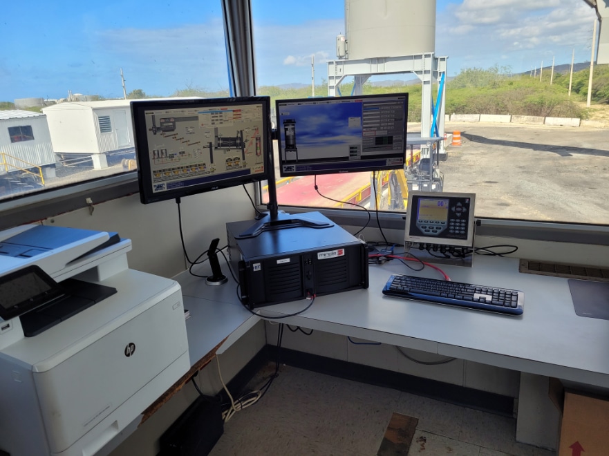
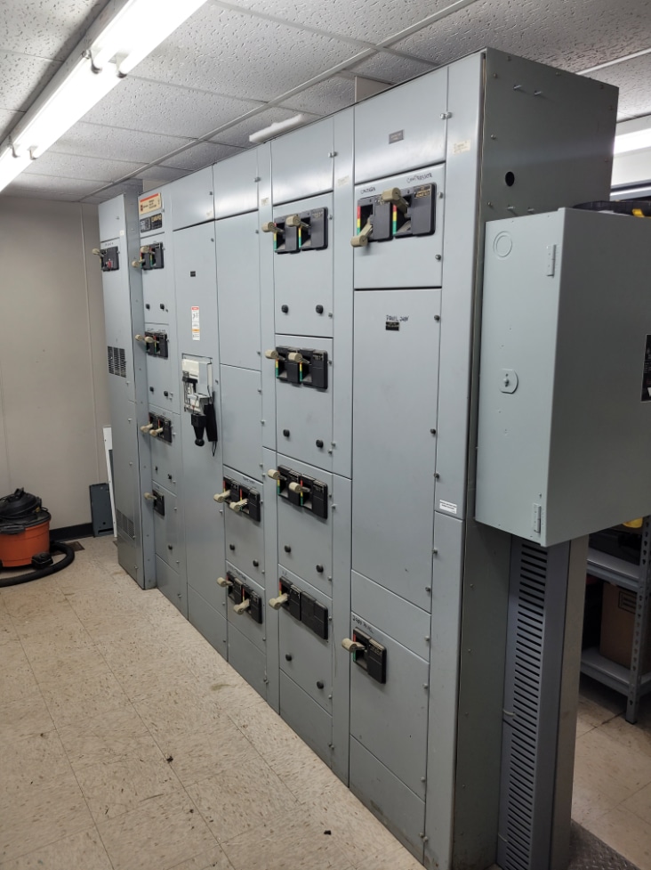
Reliable Asphalt Products located the used control house with a complete motor control center for the team. Miguel Suria is an electrical engineer and took care of installing the MINDS plant automation for the plant.

Reliable assisted Super Asphalt by getting the equipment to the Port of Jacksonsville. From there, Super Asphalt utilized its in-house ocean bound freight specialist to get the equipment shipped to the island. When Suria was asked how hard it is to get equipment from the states to the island, he responded, “It’s not difficult at all, but expensive.”

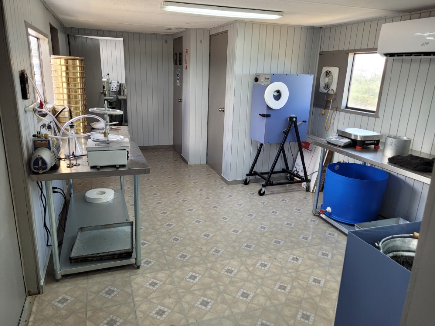
Super Asphalt has two complete labs on site. According to Suria, one is for his company, and the other is for the Puerto Rico Highway Authority’s use.

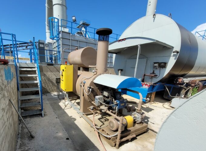
Although the plant was nearly complete and in Puerto Rico, the facility still needed a control house with motor control center, a hot oil heater and plant automation. Super Asphalt and Mauzy worked together to complete the plant.

Reliable Asphalt Products located a used control house with a complete motor control center shortly after the rest of the components were shipped to the island.

From left to right, Miguel Suria, Eduardo Enchautegui, Rawand Perez

“The used control house that Reliable found for us was an excellent option. I did not inspect it myself but got a good report from Reliable and this has worked out really well,” Suria said. Upon Reliable’s recommendation, Super Asphalt elected to purchase a MINDS automation system for this plant. Reliable also supplied Super Asphalt with a reconditioned hot oil heater to complete the plant. Although it is not currently equipped with a RAP system, there are plans to install a RAP system in the future, according to Suria.

Once the plant arrived in Puerto Rico, Super Asphalt began the permitting process. As is the case many times, this took longer than expected. Their site was prepared; however, the plant was not allowed to be erected until the permit was secured. Upon securing the permit, Suria, along with the team of Eduardo Enchautegui, plant superintendent, and Rawand Perez, plant operator, began the process of erecting the plant at the Penuelas, Puerto Rico, site.

Because these components were sourced from several locations and included some new components, installation of a plant like this can be tricky. In order to meet the permit requirements, Super Asphalt had to install two complete labs on site. According to Suria, “One is for us, and the other is for the Puerto Rico Highway Authority.”

Among his many talents, Suria is an electrical engineer. He installed the MINDS plant automation. Once he completed the plant and automation installation, Len Newton, Reliable Asphalt Products’ leading automation technician, arrived to commission the plant. According to Newton, “Miguel did an excellent job installing the MINDS system. Because of his good work, we were able to commission the plant in a very short time.”

The plant was installed very close to Super Asphalts’ liquid AC supplier and close to the job site that justified this plant purchase. After a cross country plant move, ocean bound shipping and a lengthy permitting process, Super Asphalt’s latest plant is in full operation. “Even though this is partly used, with the controls and the hard work of all those involved, we have something that we can be very proud of,” stated Suria.

5 Steps for Asphalt Plant Silo Repair

Making repairs to a worn asphalt plant silo is never fun or easy. For Dan Bowman with Tullis Inc., Redding, California, however, it was going to be an even bigger challenge. Bowman’s primary challenge came from the weigh hopper hanging directly beneath the worn silo cone, making access to the cone difficult and dangerous.

Silo repairs present a challenge starting with the choice of liner material. Do you use plate steel cut and rolled into the standard “pie” shaped kit? What about ceramics? For Bowman, the solution came in the form of the Kenco Engineering’s Modular Silo Liner Kit system from Kenco Engineering, Roseville, California.

9 Tips for Asphalt Plant Maintenance

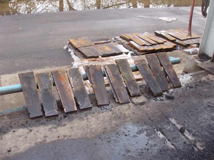
A primary factor for Tullis’ choice was that Kenco’s unique Modular Silo Liner Kit is designed to be easier to install than OEM style liner kits. Custom designed for each installation, Kenco’s kits are comprised of trapezoidal wear plates cut from ½-inch thick, AR500 plate. These wear plates are less than 24 inches long and weigh less than 25 pounds each. This size and weight combination allows for covering the maximum amount of surface area while remaining small enough and light enough to easily handle. Each plate has recesses cut into the perimeter allowing simple plug welding for installation.

Step 1. Build a base

To start his project, Bowman began by building a platform on top of the weigh hopper. This platform formed a base from which to work in the silo. The small distance between the weigh hopper and the opening for the silo would have made working with long, pie-shaped liner pieces next to impossible. The smaller Kenco kit liners, however, fit easily in this reduced work space. This photo is courtesy of Tullis Inc.

Step 2. Separate your materials

For simple round silos emptying from a round opening, the Kenco Modular Silo Liner kit consists of multiple rows of liners where each row consists of identical liners with each liner individually numbered. Bowman and his workers separated the liners according to their number and loaded them into a man basket, which they used to lift the liners up to the work platform. They built scaffolding in the silo as work progressed further up from the bottom. This photo is courtesy of Knife River Corporation.

Step 3. Weld a base ring

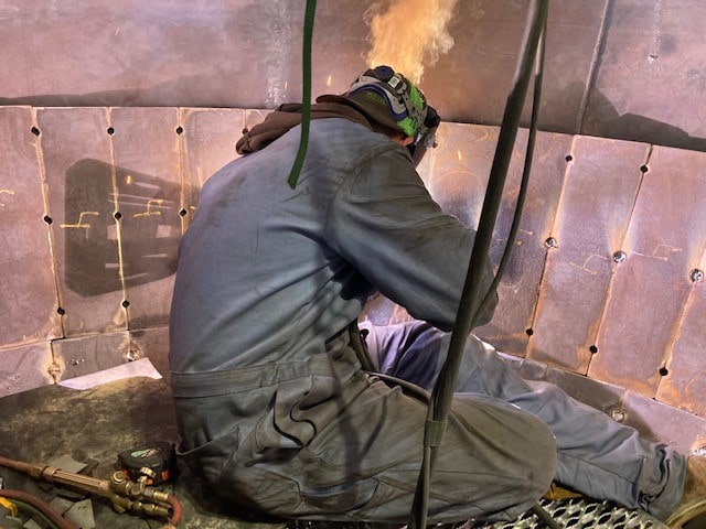
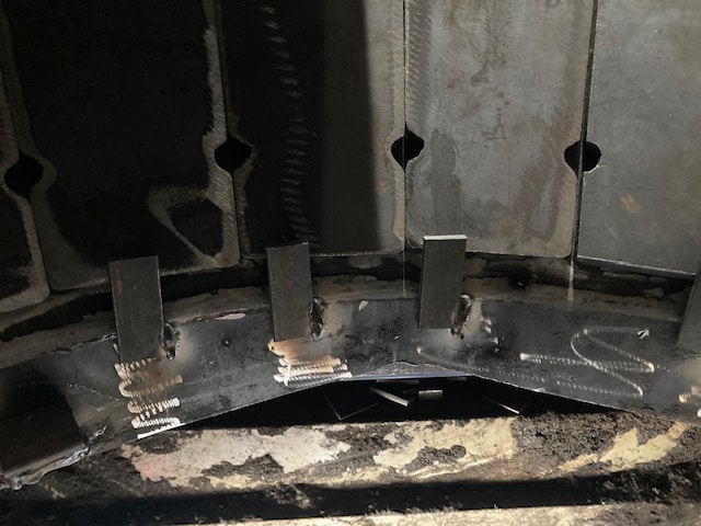
Installing the very first row took a little longer than expected because Bowman and his team first welded a base ring to the bottom of the silo to serve as the base support for the first row. This base ring, while taking quite a bit of time to build, ensured the first row could be properly positioned. This photo is courtesy of Tullis Inc.

Step 4. Tack weld

Once properly positioned, this first row was tack welded into place. At this point, the first row serves as the perfect base for all subsequent rows, which are simply stacked in place according to their row number and then tacked in place as well. This photo is courtesy of Tullis Inc.

Step 5. Build as you go

Another benefit of Kenco’s modular design is that it is not an “all or none” type of arrangement. Producers can install kits row by row over time. As an example, Bowman installed three rows of liner plates last season and plans on adding two more rows along with a cylinder band this year. All in all, Bowman was happy with the way the Kenco kit made a bad job much easier to handle.

Another asphalt producer who is happy with the performance of the Kenco Modular Silo Liner Kit is Pat Budlong with Knife River Corporation, Tangent, Oregon. At this point in his career, Budlong has been involved with installing more than 24 Kenco Modular Silo Liner kits.  Budlong’s primary motivations for using Kenco’s kits include ease of installation due to the custom design as well as the long wear life the liners provide.

How to Unclog the Asphalt Silo Safely

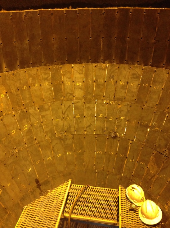
When discussing ease of installation, the Kenco kits go in fast. According to Budlong, the complete project, start to finish, will take about three days. That includes about one day to complete the Confined Space process, make the silo safe and install the scaffolding used to weld in the liners. Day two usually takes about 10-12 hours and is when the Kenco kit is welded into place including a full weld along the top edge to prevent material getting behind the liners to “hydraulic” them away from the wall. Day three will be for finishing up what is left and disassembly of the scaffolding. Budlong contends that when relining a silo in the air, the Kenco Modular Silo Liner kit is “faster to install and wears great.”

When looking at wear life, the Kenco Modular Silo Liner kit is also a long-term solution to a maintenance headache. Made from ½-inch-thick AR-500 plate, the Kenco kits have been found to outlast pie-shaped liner kits by more than 3-1. When compared to ceramic kits, Kenco’s system can be installed in a fraction of the time due to the reduced number of components, no need for adhesive and no need for weld washers. Kenco steel liners are not susceptible to breakage.

Budlong jokingly explained that he feels bad for Kenco’s Regional Sales Representative, Paul Weber.  “I feel bad so often having to tell Paul that I don’t need anything—nothing is worn out.”

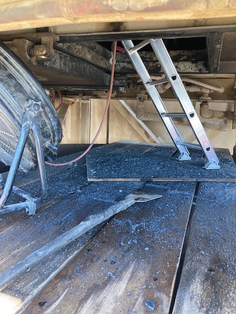
A few days of hard work result in a newly lined interior, ready for next season’s production. Photo courtesy of Kenco Engineering.

How to Control Dust During Production

The father-son team of Lloyd and Jason Vivant ran the plant for McNamara Contracting in Rosemount, Minnesota, 25 years ago. Lloyd wanted to control the amount of dust going back to his mix evenly and reject the difference. He set up a system to do just that.

Today, the system design still works well for Jay. The size of the bin has increased to take on unwashed material. The savings from not washing material is threefold:

  1. Cost of washing is abated;
  2. Plant production rates are increased with drier material; and
  3. Energy use decreases with drier material.

Because the minus 200 dust product may vary excessively at times, this can be an ideal opportunity to reject the excess. Let’s look at how you might do this at your facility.

The aggregate drying process inherently separates the fines from the on-spec material. When air velocity changes, whether that’s due to production, moisture or temperature variations, through the dryer, so does the size and amount of fines separated. Consequently, the loading of the baghouse changes and so does the amount of dust returned.

Complicating the issue further is the baghouse discharging the dust in sags and surges, which can be as high as plus or minus 21% over a three-minute period. Adding insult to injury, the hot stops allow the bags to relax when the fan is turned off causing most of the dust to fall and fill the auger below. When the plant is started again, the dryer initially sees the full auger surge (+59%).

Bomag’s ION Dust Shield

Because the bags had released most of their dust, the augers run empty until the bags build up the dust cake again. This situation then causes the dust to go from the surge to a sag (-59%) until it slowly builds up the dust cake over a five-minute period.

There are some basic steps the plant operator must execute to ensure he isn’t chasing ghosts and is getting the correct fines metered back to the drum. Let’s look at those steps.

  1. Practice correct operating procedures, which involve slowly changing from one production rate—or temperature—to another, maintaining consistent aggregate moistures, and slowly changing exhaust damper or fan speed settings.

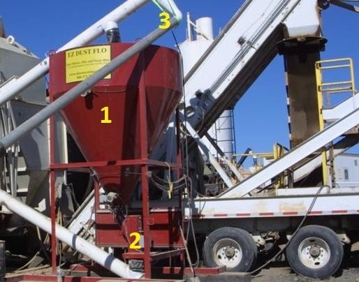
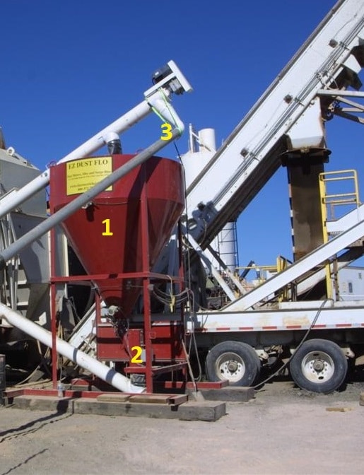
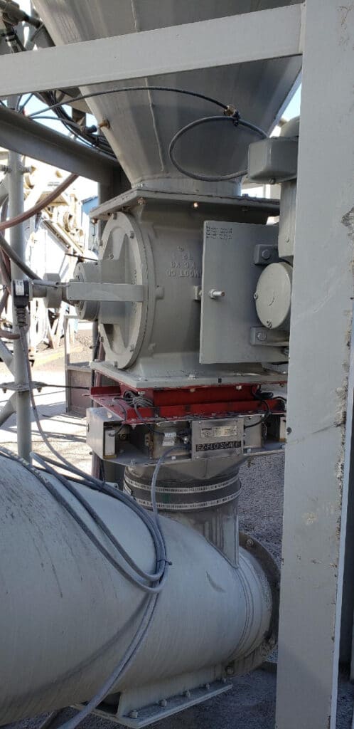
  1. Invest in the right equipment, such as a surge bin with flow measuring and control. You want the baghouse dust to be continuously fed to the surge bin (indicated by the number 1 in the photo). In order to use all the dust while smoothing all the sags and surges, the operator will set his vane feeder discharge speed so the level fluctuates between the low and middle-level bindicators during normal operation and between the lower and high-level bindicators during a hot start. Notice the change in bin-level tolerance is significantly different between steady production and startups; startups can take the system five minutes to recover. It’s that five minutes of dust that forces us to use the extra volume available in the storage bin. The surge bin should be sized to absorb these fluctuations. When rejecting dust, the operator can set the dust flow controller to the percentage wanted. The flow scale (indicated by the number 2 in the photo), reports to the controller and increases or decreases the vane feeder depending on the plant rate. The excess fills the surge bin and is rejected out the second surge bin auger discharge port.

These systems usually are added as a retrofit. The gray vertical picture below shows the controlling device to be regulated by the plant blending control by what is passing through the scale below. Owners should specify the control scheme they want their blend control to respond to. The author suggests the procedure below to get the full benefit from the new equipment. Remember, the control mode position switch has three options: feed/reject; sag/surge; and manual.

Jay Vivant still uses the system his father set up to meter the amount of dust going back to his mix in an even, controlled fashion while rejecting the difference.

The plant blending control regulates the controlling device, controlling what is passing through the scale below.

Mode 1. Reject Excess Dust

In Mode 1, the dust bin with an auger dust spillover, the discharge port is used to automatically reject what the vane feeder does not take away (i.e., the dust the plant does not use as a percentage of dust being added to the mix). The vane feeder is controlled by the plant blending computer in a closed-loop PID type control to setpoint percentage of material delivered to the drum as measured by the rate of flow through the continuous weigh scale. If this mode is selected and the percentage is set too high, some of the sags and surges will pass through. Upon hot start, the blending control should “remember” what the speed was when hot stopped and held for preset time for major surge-sag to pass and then release to PID control. (Upon hot stop, the bags usually release much of the dust held up in bags when fan airflow is stopped, and this fills the bottom augers. It will take the bags another baghouse cycle time to recharge the bags.)

Mode 2. Sag/Surge Control

In Mode 2, the speed of the vane feeder is based on finding the average speed it takes to keep the level of the bin as close to mid-level as possible (at least to keep from reaching high or low levels). If you experience a high-level bindicator (dry contact closure) reading, the speed signal should increase (preset adjustable speed up signal). Low-level bindicator (dry contact closure) should slow the speed signal down (preset adjustable speed down signal). Mid-level bindicator (dry contact) should give the operator an idea of how fast the bin is filling or emptying to help in setting where preset adjustable speeds should be set.

Aggregate Industries Uses Crucial International Control Systems

Mode 3. Manual Control

In Mode 3, the operator adjusts the speed as he sees fit. Unfortunately, operators usually set the vane feeder to keep the bin near empty, which defeats the purpose of all this equipment. For controlling surges, set the speed so the bin does not run empty and minimizes the time the bin is rejecting. When rejecting, feed the plant what it needs and everything else takes care of itself.

Dust should be controlled as closely as cold feed bins, and in some cases more closely. This is a great system to improve your mix quality.


For more information, contact Clarence Richard at (612) 590-0993.

How to Get the Most out of Your Asphalt Pump

The varying properties of asphalt make standard pumping technology ill-equipped to tackle the challenges asphalt poses. That’s why having the right pump is just the start. You must follow best practices and procedures to successfully handle asphalt. This article will review the proper procedures to process this challenging substance while getting the most out of your asphalt pump.

Asphalt comes in several variations, with each creating unique challenges for pumps. The most common—liquid asphalt cement (AC) for use in hot-mix asphalt (HMA)—is used heavily in paving projects. AC’s main challenge in the production process comes from temperature variations that can alter its viscosity, making it challenging for standard pumps to reliably process.

Emulsified asphalt—composed of a mixture of AC, an emulsifying agent (surfactant) and water—is prone to shearing. Pumps that handle it need extra internal clearances, the ability to operate at a reduced speed and, in some cases, be fitted with special idler-bushing lubrication methods.

Filled asphalt, also called coating asphalt, contains limestone or other abrasive particle concentrations of 60 to 70%, making them very abrasive. Pumps that process filled asphalt typically require hardened cast-iron or tungsten-carbide bushing sets, as well as a hardened case, head, rotor gear and idler gear to maximize pump life and increase productivity. The pump speed should also be reduced when handling this abrasive asphalt to optimize component life.

Jacketing for Optimal Efficiency

As we know, asphalt pumps must maintain specific thermal conditions to ensure proper functionality. That’s why heat distribution becomes essential, and this can be accomplished with jacketing.

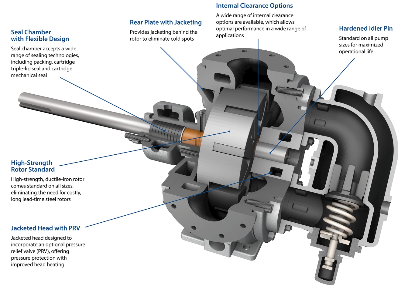
The key is identifying your problem areas or cold spots, which become problematic over time when handling asphalt. The most common cold spot on an asphalt pump is behind the rotor, as well as the rotor bearing sleeve. Neither spot transfers much asphalt, which also means they don’t retain heat. In other words, these are dead zones that should be a priority for jacketing.

The first area to jacket should be the rotor bearing sleeve, given its importance to the entire system. If the liquid asphalt becomes cold in that area, the substance could solidify and make it difficult for the pump to turn, or worse, damage the pump internals.

Solve the Way You Pump Asphalt

The area directly behind the rotor is similarly important. Many pumps do not have jacketing in this critical area and as a result, asphalt often solidifies here after the pump has cooled. Failure to heat this area will prevent the pump from starting properly and may cause damage or failure. After start-up, continuing to heat this critical area helps to maintain fluid temperature and viscosity in this specific area of the pump, ensuring the highest level of efficiency and performance. Neglecting the area behind the rotor and permitting cool asphalt to set will at minimum reduce efficiency and may result in damage to the pump.

In addition to heating the critical areas of the pump, upstream and downstream piping are also important. The piping typically has some type of heating applied to all or most of the piping (hot oil, steam or electric elements) as well as insulation to retain heat. Because the time required to completely heat the AC to a liquid state in the pipe is less than within the pump, the pump is often the last to come up to temperature unless additional jacketed areas on the pump are used. However, in the event a cooled slug of asphalt does break loose in the piping or pump, it can cause some type of blockage or restriction. This condition poses a challenge to the pump if it is on the discharge side, causing an increase in pressure, or on the inlet side, starving flow into the pump inlet. It will begin to soften as the hot asphalt flows past even if it is at a low flow. Once the cooled piece of AC is hot enough to mix with the liquid AC, the pump can operate in the most optimal conditions. A robust start-up procedure allowing both the pump and piping to come up to temperature, at which AC is completely liquid, is best to avoid these issues.

Jacketing becomes even more important when linking several pumps together—in parallel or a series—for asphalt applications. Both options require plumbing between the pumps, which automatically creates spots—the entry and exit points—prone to losing heat.

When linking pumps in series, there are a few considerations. The first is to identify the known cold spots—usually the area behind the rotor—and jacket them accordingly. You’ll also want to start your series run on the back side of the case, run it to the rotor bearing sleeve and then run it to the head and valve and finally to the hot oil supply. That’s one scenario designed to provide even heating throughout the series of pumps.

A parallel setup, while more difficult to establish, tends to provide better temperature uniformity throughout the entire pump rather than a gradient. While it’s not as common as a series setup, if it works for your application, it offers consistent temperatures throughout the pump.

Overall, jacketing the cold spots in an asphalt pump ensures that heat stays in the pump to keep the product at the proper temperature. This keeps the pump running optimally and efficiently. The more jacketing that you have, the more heat you can throw throughout the entire pump.

Start Up and Run Speed
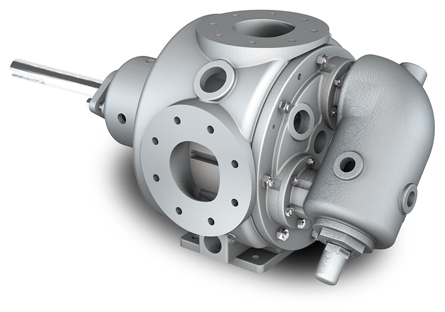
The V2-423 pump from EnviroGear

Running a pump cold isn’t ideal in many applications, but especially not when it comes to processing asphalt. Operators want to have a heated pump when asphalt passes through. Otherwise, they run the risk of cooled asphalt bonding and sticking to the pump internals.

If you start a cold pump (one that has just returned from service or repair) without jacketing, you run the risk of the cold asphalt restricting flow in the pump and lines.  Without proper heating, solidified asphalt restricts flow through the pump, which in turn increases the discharge pressure until the pump reaches steady state flow. This over-pressure condition is problematic especially for pumps without thrust control. Without thrust control, the over-pressure condition can cause the rotor to thrust axially, which may damage the rotor, idler gear or head. This ultimately leads to premature wear or damage and the need to repair or replace the pump.

Maintaining process temperature in the pump also ensures a lower viscosity for asphalt, which in turn allows the operator to run the pump at higher speeds. In a non-jacketed or inadequately jacketed pump, the loss of heat means the asphalt will cool down and solidify, limiting the ability to run at higher flow rates. Operators will need to remedy this by slowing the pump down to avoid damaging it. Slower pump speed results in lower efficiencies, loss of production, and likely results in lower profitability.

In a properly jacketed pump, an operator can run the pump at higher speeds because maintaining temperature keeps the asphalt at the proper viscosity. The asphalt can thus pass through the pump at increased flow rates without damaging the equipment. By optimizing jacketing to maintain temperatures within the pump, an operator can maximize the speed and flow of the pump while reducing maintenance and replacement costs.

Tsurumi America Launches New Website for Pumping Specialists

Internal Debate

The internal composition of your pump also plays a major role in its functionality in asphalt applications. The rotor is the driving pulse of the pump and must be specified appropriately for your application. Cast iron rotors are common, but conditions like abrasives and higher pressures may dictate the need for something more robust. While steel is strong and durable, it is also more costly than other materials that offer similar properties. Ductile iron offers comparable properties to steel, but with a lower price point. Ductile iron, like steel, can handle the changing composition and abrasive nature of asphalt without compromising its performance or durability. It also allows the handling of higher pressures and temperature conditions.

Ductile iron can be used across the pump, including the surface hardened case, the pump head, the rotor, idler and shaft. Regardless of asphalt type, ductile iron has the strength and integrity to handle it. It also ensures long pump life.

Another important consideration is internal clearances. Internal components endure significant stresses when pumping asphalt. With incorrect clearances, common failures can occur from the bushing, gear or shaft. Without the proper clearances or material composition, viscosity changes from temperature swings can cause asphalt to solidify in the pump or piping system, causing rotor gear-tooth failure.

Rebuild or Replace

Pumps can’t last forever, but their life can be extended depending on how well the operator takes care of them. Generally, routine maintenance remains the best option for getting the most out of your asphalt pump.

But as time goes on and performance begins to suffer, the choice tends to come down to two options – rebuild or replace. Typically, pressure loss serves as a prime indicator that something needs to be fixed on a pump. When a pump can’t build pressure and can’t make flow to overcome pressure losses, that’s usually a sign that it needs a rebuild.

Naturally, these pressure losses could come from several culprits, such as bushing wear, rotor wear and/or head wear. Of course, these things are unknown until an operator opens the pump to see what’s causing the problem. If it’s a component or two, then a rebuild makes the most economic sense.

An inspection, however, can also show that more than a few components will need to be replaced. A single bushing or seal repair won’t negate a replacement, but if more than two components are at fault, the price point begins to inch closer to purchasing a replacement.

While replacement of a pump will eventually occur, the best way to prevent it from happening prematurely is to keep asphalt pumps at the optimal temperature with jacketing while making sure to do the scheduled maintenance.

Asphalt can be a difficult substance to pump given the requirements to ensure smooth flow and pump longevity. Proper care and operation are the best practices to get the most out of your asphalt pump for at least a decade, if not longer.

Michael Coburn is the product manager for EnviroGear®. He can be reached at Michael.Coburn@psgdover.com. Jeff Petersen is the business development manager for EnviroGear in North America. He can be reached at Jeff.Petersen@psgdover.com.