How to Control Dust During Production

The father-son team of Lloyd and Jason Vivant ran the plant for McNamara Contracting in Rosemount, Minnesota, 25 years ago. Lloyd wanted to control the amount of dust going back to his mix evenly and reject the difference. He set up a system to do just that.

Today, the system design still works well for Jay. The size of the bin has increased to take on unwashed material. The savings from not washing material is threefold:

  1. Cost of washing is abated;
  2. Plant production rates are increased with drier material; and
  3. Energy use decreases with drier material.

Because the minus 200 dust product may vary excessively at times, this can be an ideal opportunity to reject the excess. Let’s look at how you might do this at your facility.

The aggregate drying process inherently separates the fines from the on-spec material. When air velocity changes, whether that’s due to production, moisture or temperature variations, through the dryer, so does the size and amount of fines separated. Consequently, the loading of the baghouse changes and so does the amount of dust returned.

Complicating the issue further is the baghouse discharging the dust in sags and surges, which can be as high as plus or minus 21% over a three-minute period. Adding insult to injury, the hot stops allow the bags to relax when the fan is turned off causing most of the dust to fall and fill the auger below. When the plant is started again, the dryer initially sees the full auger surge (+59%).

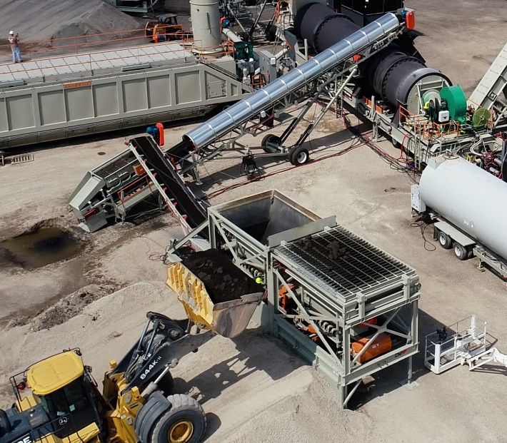
Bomag’s ION Dust Shield

Because the bags had released most of their dust, the augers run empty until the bags build up the dust cake again. This situation then causes the dust to go from the surge to a sag (-59%) until it slowly builds up the dust cake over a five-minute period.

There are some basic steps the plant operator must execute to ensure he isn’t chasing ghosts and is getting the correct fines metered back to the drum. Let’s look at those steps.

  1. Practice correct operating procedures, which involve slowly changing from one production rate—or temperature—to another, maintaining consistent aggregate moistures, and slowly changing exhaust damper or fan speed settings.
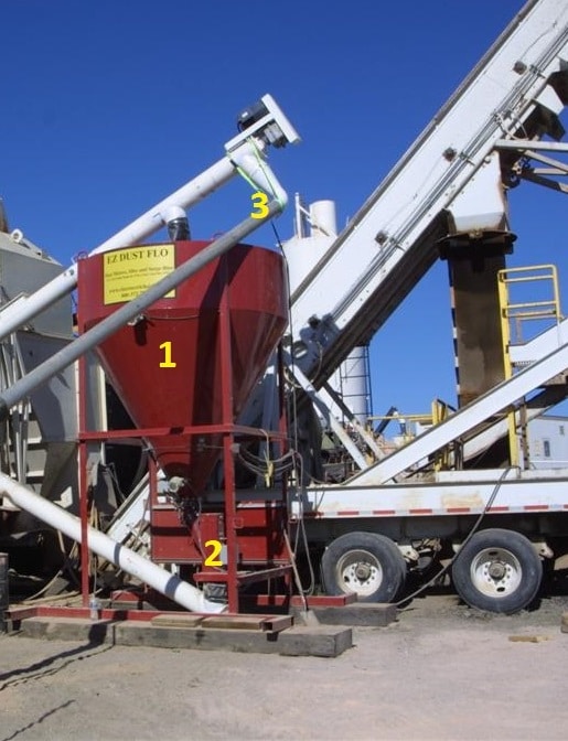
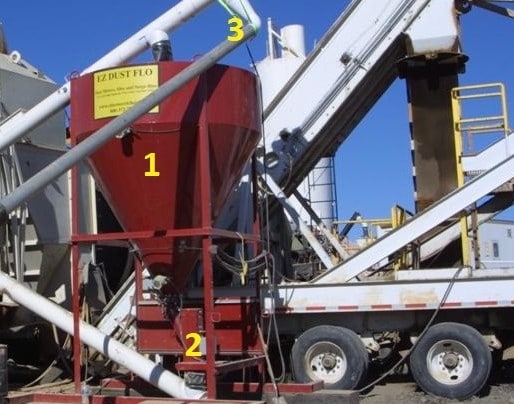
  1. Invest in the right equipment, such as a surge bin with flow measuring and control. You want the baghouse dust to be continuously fed to the surge bin (indicated by the number 1 in the photo). In order to use all the dust while smoothing all the sags and surges, the operator will set his vane feeder discharge speed so the level fluctuates between the low and middle-level bindicators during normal operation and between the lower and high-level bindicators during a hot start. Notice the change in bin-level tolerance is significantly different between steady production and startups; startups can take the system five minutes to recover. It’s that five minutes of dust that forces us to use the extra volume available in the storage bin. The surge bin should be sized to absorb these fluctuations. When rejecting dust, the operator can set the dust flow controller to the percentage wanted. The flow scale (indicated by the number 2 in the photo), reports to the controller and increases or decreases the vane feeder depending on the plant rate. The excess fills the surge bin and is rejected out the second surge bin auger discharge port.

These systems usually are added as a retrofit. The gray vertical picture below shows the controlling device to be regulated by the plant blending control by what is passing through the scale below. Owners should specify the control scheme they want their blend control to respond to. The author suggests the procedure below to get the full benefit from the new equipment. Remember, the control mode position switch has three options: feed/reject; sag/surge; and manual.

Jay Vivant still uses the system his father set up to meter the amount of dust going back to his mix in an even, controlled fashion while rejecting the difference.
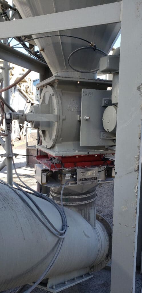
The plant blending control regulates the controlling device, controlling what is passing through the scale below.

Mode 1. Reject Excess Dust

In Mode 1, the dust bin with an auger dust spillover, the discharge port is used to automatically reject what the vane feeder does not take away (i.e., the dust the plant does not use as a percentage of dust being added to the mix). The vane feeder is controlled by the plant blending computer in a closed-loop PID type control to setpoint percentage of material delivered to the drum as measured by the rate of flow through the continuous weigh scale. If this mode is selected and the percentage is set too high, some of the sags and surges will pass through. Upon hot start, the blending control should “remember” what the speed was when hot stopped and held for preset time for major surge-sag to pass and then release to PID control. (Upon hot stop, the bags usually release much of the dust held up in bags when fan airflow is stopped, and this fills the bottom augers. It will take the bags another baghouse cycle time to recharge the bags.)

Mode 2. Sag/Surge Control

In Mode 2, the speed of the vane feeder is based on finding the average speed it takes to keep the level of the bin as close to mid-level as possible (at least to keep from reaching high or low levels). If you experience a high-level bindicator (dry contact closure) reading, the speed signal should increase (preset adjustable speed up signal). Low-level bindicator (dry contact closure) should slow the speed signal down (preset adjustable speed down signal). Mid-level bindicator (dry contact) should give the operator an idea of how fast the bin is filling or emptying to help in setting where preset adjustable speeds should be set.

Aggregate Industries Uses Crucial International Control Systems

Mode 3. Manual Control

In Mode 3, the operator adjusts the speed as he sees fit. Unfortunately, operators usually set the vane feeder to keep the bin near empty, which defeats the purpose of all this equipment. For controlling surges, set the speed so the bin does not run empty and minimizes the time the bin is rejecting. When rejecting, feed the plant what it needs and everything else takes care of itself.

Dust should be controlled as closely as cold feed bins, and in some cases more closely. This is a great system to improve your mix quality.


For more information, contact Clarence Richard at (612) 590-0993.
9 Tips for Asphalt Plant Maintenance

To give hot-mix asphalt (HMA) producers a primer on current upkeep options, we’ve assembled a handful of priority maintenance items that original equipment manufacturers (OEMs) and service providers were willing to outline. The following concepts walk you through the basics of greasing, silo wall monitoring, odor reduction installation, recycled asphalt pavement (RAP) system maintenance, trunnion adjustment and more.

In alphabetical order by OEM, the following topics will help you get your winter maintenance program planned.

1. Ammann Group Suggests Protecting the Plant with Greasing

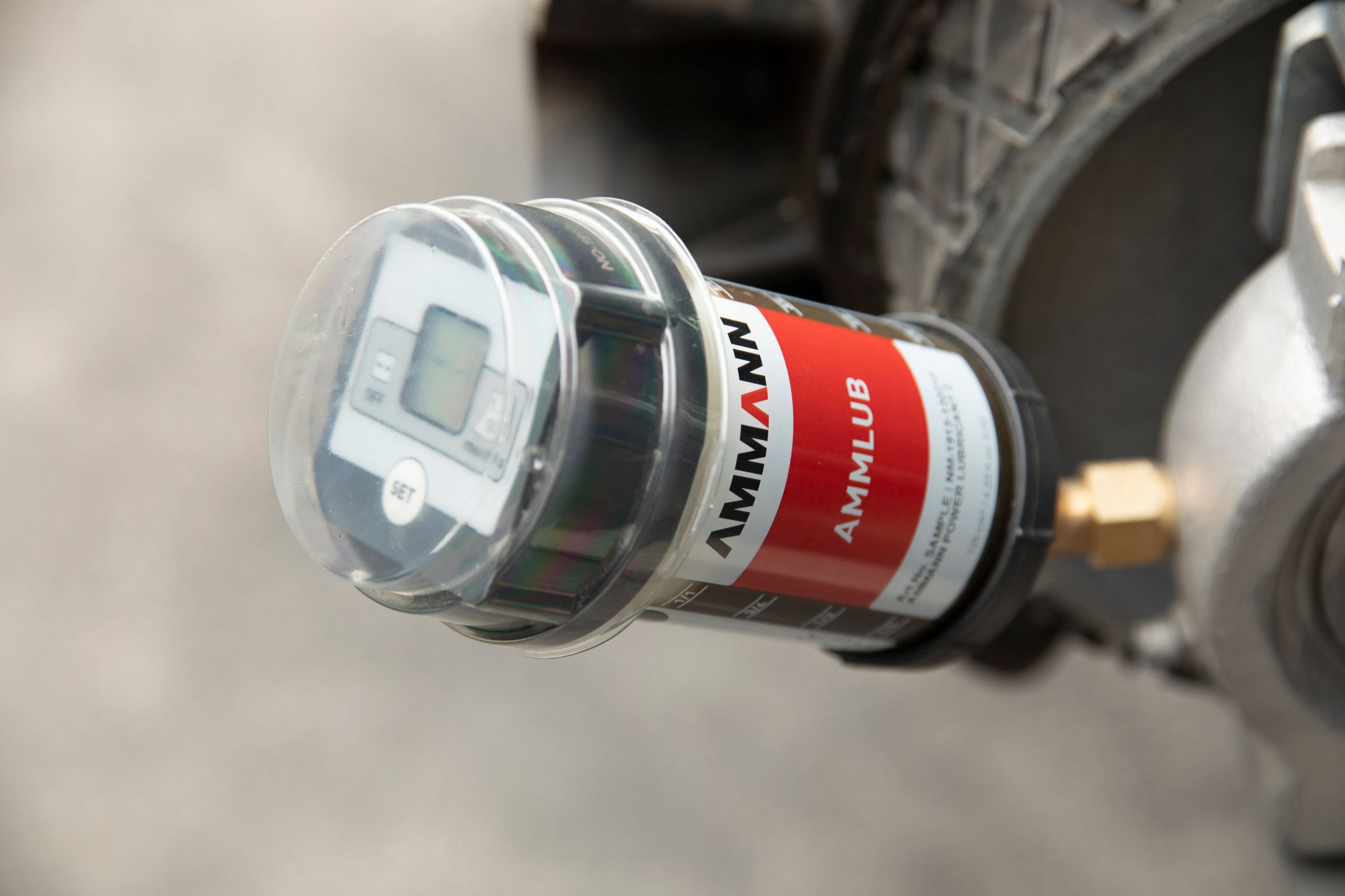
The Ammlub device from Ammann Group is mounted directly on the plant’s lubrication points.

All asphalt production businesses want to minimize the cost of ownership. The lower those expenses, the more competitive asphalt prices can be—and the higher profits can go. Ammann’s efforts to reduce asphalt operating expenses include Ammlub, which is Ammann’s automatic lubrication system, designed to provide three key benefits: longer plant life, reduced fuel costs and improved safety.

Traditional lubrication methods can be a struggle. They often require that technicians stretch and strain to reach extremely tight spaces—and that they fight dust, dirt and heat in the process. There also is the question of when to grease and how much grease to apply.

The labor-saving Ammlub system is mounted directly on the plant’s lubrication points. It automatically applies lubricants at scheduled intervals, ensuring that the process is done on time—every time. In addition, Ammlub eliminates downtime.

Fix a Torn Conveyor Belt

The lubricant applications can occur while the plant is running, enabling completion of the routine maintenance without a drop in productivity.

An immediate benefit is fuel savings, which can be reduced as much as 10 percent when all parts and components are working harmoniously.

With appropriate lubrication, those parts and components will also last longer, providing further savings. Because this system also locks out contaminants, plant life is extended, too.

Workplace safety is improved as well. Technicians no longer need to lug tools and fluids with them to access difficult-to-reach service points. These service points typically include all components along the process flow, starting with the cold feeder and ending with the discharge shoot.

For more information on the Ammlub product, contact simone.franz@ammann.com or visit www.ammann.com.

2. Astec Walks You Through Silo Maintenance Service

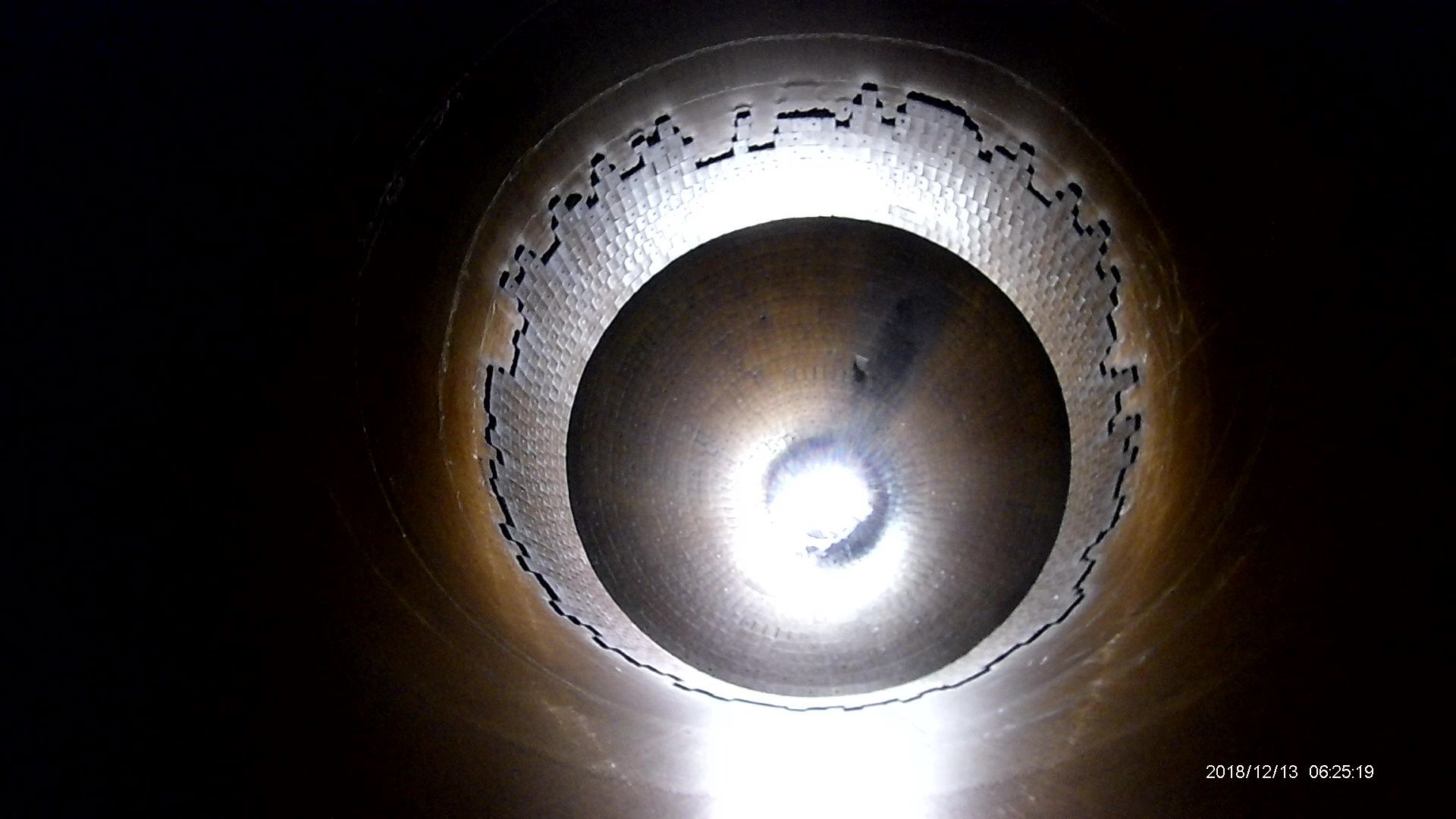
Inside this silo, a large hole is forming directly above the ceramic tiles. Areas like these were found along the entire circumference of the silo. Photo courtesy of Astec Industries

The team at Astec saw the need to make silo inspections safer and developed the SiloBot inspection device—a robot that is placed inside a silo by a trained inspection technician who then stays safely outside of the silo while performing a thorough inspection of the silo interior. A SiloBot inspection takes less than two hours to fully inspect all silo welds. With regular inspections, you can perform preventative maintenance that extends silo life.

Astec Engineering recommends having full silo inspections performed every two years, minimum. For high production facilities and silos that are 10 years or older, it is recommended to inspect annually.

Four Steps for Cleaning Disc Springs

Astec offers a recurring inspection plan for every 1-2 years that will allow us to provide the customer with comparative data. This data will help customers forecast wear in their silos so that preventative maintenance can be performed, giving them the ability to avoid spending unnecessary funds on more severe failures. Inspections can still be given on a one-time basis, as well.

Along with non-destructive thickness measurements, the SiloBot inspection device also checks for missing ceramic tiles, weld seam separation, damage to liner sections, holes in silo walls, batcher gate issues and other issues resulting in acute wear inside the silo.

One technician travels with two SiloBot inspection devices, software, a winch and mount, tools required for SiloBot device maintenance, and a truck with a mounted scissor lift in the bed. Customers are not required to rent manlifts.

The technician inserts the SiloBot through the mouth of the silo using a winch that is mounted on top of the silo (used as a safety tether and connected to the bot at all times) and the scissor lift mounted in the back of the truck. The incredibly strong natural magnets in the wheels allow the bot to traverse over ceramic tiles and onto the silo wall.

The large amount of missing ceramic tiles from the silo wall has allowed mix to wear the silo metal acutely in many areas. Multiple holes were found in this silo. Photo courtesy of Astec Industries

The SiloBot inspection device gathers data by utilizing a steel brush and motor to clean the silo wall prior to taking measurements with an ultrasonic thickness gauge. The data is then sent via a telemetry system linked to the technician’s laptop computer. This data is transmitted in real time, allowing the technician to view the results and fine tune the inspection as he goes.

Inspections range from 30 minutes to one hour, depending on the size and condition of the silo. The customer receives full 1080p HD video of each silo inspection on the day of inspection. The final report, delivered via e-mail in an average of 7-10 days, will include the raw data points, a graph that illustrates the location of these data points, and a written report with pictures that reference issues noted in the report. The report also features specific recommendations for repair.

SiloBot inspections can only be performed by a trained Astec technician due to the sophistication of the device and its components. Astec SiloBot Technician Alex Harrison said, “For customers with many plants, we devote ample time to get all of their inspections completed before moving to the next customer.”

If repairs are necessary, the repairs can be scheduled through the Astec Service Department or the customer can perform the repairs themselves.

To get information on the SiloBot inspection service, call on your regional Astec Parts or Capital Salesperson, or contact Alex Harrison directly at (423) 356-4791.

3. Brock Tells You When It’s Time to Change the Bags

While Nomex bags are most common for HMA plant operations, the industry veterans at BROCK recommend an analysis of the plant’s overall operation and mix designs to assess the right bag for the application.

There are a lot of factors that affect the life of a baghouse bag and factors will likely be different at each plant site. Bag material, operation temperature, gas stream content, dust size, air-to-cloth ratio, cleaning effectiveness and bag fit all contribute to how long bags might last and when it is time to change them out.

The team at BROCK recommends inspecting baghouse bags at least once per year, but preferably two to three times per year. We especially recommend checking bags as frequently as reasonable when the operation uses—or changes to using—diesel or heavy fuel oil in their drying process, as the lack of atomization in the burning process can lead to oil in the dust and, eventually, on the baghouse bags.

Things we advise to look for, bag wise, are change in bag color, visible changes to the outside texture of the bags, holes in the bags, and shrinkage in the bags. One key data point operators can use to measure the overall effectiveness of the baghouse, along with the bags themselves, is to measure the differential pressure in the baghouse. It can be a leading indicator of bag and/or dust system issues. Of course, dust coming out of the baghouse stack is the easiest to see with the human eye as a key indicator of bag issues.

Solve Asphalt Cement Tank Wear

There have been several bag types introduced to the industry over the last 30 years and the technology behind them has made great strides in that time in an effort to keep up with the changes in mix designs. Changes in mix designs include increased RAP percentages, stone matrix asphalt, open graded mixes, asphalt rubber, glass, roofing shingles (RAS) and warm mix, among others. These all affect plant operating temperatures, dust types and dust volumes the baghouse experiences.

Bags that are commonly found in today’s hot-mix asphalt production world include 14 oz. Nomex, Nomex singed, micro denier, hydro entangled, and P84, for higher temperature applications. Nomex singed is the bag we have seen that fits the most common needs of plants; however, we do recommend an analysis of the plant’s overall operation and mixes produced to assess the right bag for an individual plant.

For more information about plant assessments, contact Travis Sneed, vice president of sales and operations, BROCK, at tsneed@brock.industries or visit www.brock.industries.

4. Butler-Justice Shares Blue-Smoke Elimination

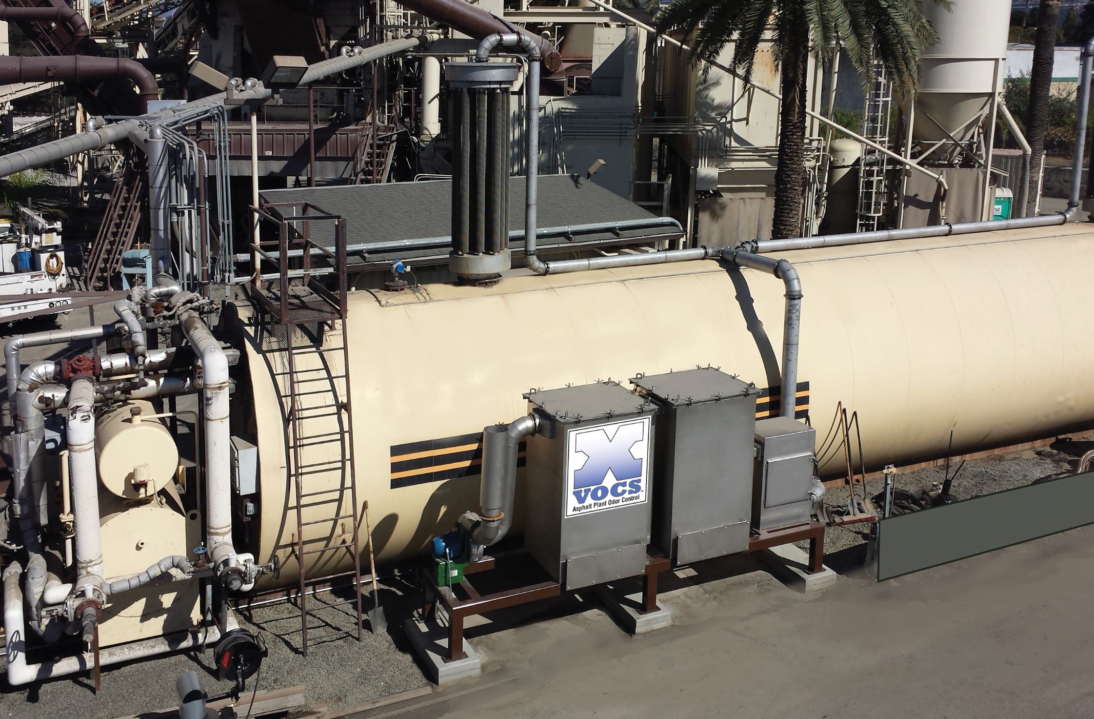
The X-VOCS system from Butler-Justice

As plants move toward the winter season, right now is an ideal time to assess any impacts from blue smoke and odors. Emissions from plants—both the classic, visible blue smoke and invisible volatile organic compounds (VOCs)—can cause challenges for producers, ranging from regulatory requirements to overt opposition from neighbors. Blue Smoke Control, a division of Butler-Justice Inc., Anaheim, California, offers two systems that, between them, is designed to eliminate both issues.

According to Mike Butler, president of Butler-Justice, “The addition of RAP, rubberized asphalt and polymer blends into asphalt mix designs has led to higher emissions due to higher mix temperatures.” His company now provides environmental control devices that can be installed at the asphalt plant to remove up to 99.9 percent of blue smoke, as well as the odors associated with asphalt production. Here’s how:

The Blue Smoke Control system captures blue smoke from emission points in the asphalt production process. Because blue smoke is essentially vaporized oil at high temperatures, Blue Smoke Control’s ducting system bleeds ambient (outside) air at key points. Seven stages of filters help to coalesce the tiny oil vapor droplets and aerosols into larger droplets that can be filtered out by the blue smoke collector. The oil droplets drain from the filters via gravity to a collecting sump.

Train New Operators to Unplug Screens

In addition, the company offers its X-VOCS system, which features proprietary carbon absorption technology designed to filter and remove up to 99 percent of odors and VOCs, such as Hydrogen Sulfide (H2S), from the hot asphalt storage tanks. The X-VOCS incorporates a five-stage filtration system. In the first three stages, a series of filters remove more than 95 percent of targeted particulates down to 0.3 microns. In the final two stages, carbon filtration beds remove remaining odors and volatiles.

When the X-VOCS technology is coupled with the Blue Smoke Control system, emissions from HMA plants can be reduced to nearly zero, providing owners with the means to achieve the highest level of environmental stewardship.

Implementation of this technology has been proven to virtually end calls from nearby neighbors regarding odor and visual emissions. Both the Blue Smoke Control and X-VOCS systems can be incorporated into new plant designs, and they are also easily retrofitted into existing plant operations, with minimal modifications to the plant.

For more information on the X-VOCS system, contact mikeb@butlerjustice.com or visit www.bluesmokecontrol.com.

5. CWMF Offers Tips to Care for Your RAP System

Make sure seasonal maintenance includes a close look at your RAP system. Photo courtesy of CWMF

You can take preventative measures during the winter season to ensure a smooth process in the spring. Being proactive saves money and headaches when it’s time to start back up. Executing a preventative maintenance schedule for your RAP System in the winter, can lead to smooth sailing in the spring. Maintenance looks different for everyone, so here are some generalized tips to help reduce problems when it’s time to start running again.

The main components of a RAP system consist of the bins, collector belt, Tremor Shaker, Honey Badger hammermill, and scale conveyor. As a reference, the team at CWMF suggests looking through your manufacturer’s manual for specific maintenance recommendations. Additionally, you can follow these tips to help create your maintenance schedule.

Start by checking the obvious. Are your belt idlers functioning properly? Inspect the belt scraper, checking to see if the blades need replacement and if they’re set at the proper tension. Check for any tears in the belt splices and determine whether they should be repaired or replaced. Inspect all flashed or sealed-in areas to see if they are worn or need to be replaced. Check the shape of the screen cloth. Is it worn? Does it need replacement?

How to Unclog the Asphalt Silo Safely

If you’re using a Honey Badger hammermill for oversized RAP, the consumables should be inspected, including hammers and liners. Look at wear life for both, and if replacement is needed. All drives should be checked for fluid levels in the reducers, and the shape of the v-belts. Make sure guards are intact.

The belt scale should be inspected and calibrated (go through the calibration process to verify proper function prior to startup). An accurate belt scale results in a quality mix.

Finally, check all electrical switches, i.e. limit switches and e-stop cable pulls for proper function.

This maintenance may seem small or tedious, but in the long run these are the things that tend to get overlooked, causing delays in the startup process resulting in costly downtime. Be sure to take time and follow your preventative maintenance schedule. Maintaining the proper functioning of your RAP system will help ensure your startup runs smooth like a freshly paved road.

For more information on the RAP system from CWMF, contact Travis Mick at sales@cwmfcorp.com or visit www.cwmfcorp.com.

6. Gencor Makes You an Energy Star

As Dennis Hunt, vice president of Gencor Industries, Orlando, Florida, often says with regard to anticipated performance of a hot mix asphalt (HMA) plant in response to design and operational changes, “it depends.” This very much applies to plant energy efficiency and fuel consumption. Per Hunt, there are numerous operating variables affecting energy efficiency and fuel consumption. These include: moisture content of the virgin and recycle feed stocks, counter-flow dryer virgin material veiling pattern, main exhaust temperature (waste heat), and use of warm-mix systems. While Gencor Industries works with its customers to optimize system performance, ultimately it is the responsibility of the end-user to run the plant in an energy-efficient manner.

One energy-efficiency measure that can, and is, integrated into HMA plants by the original equipment manufacturer (OEM) is insulation. Baghouses are insulated to prevent undesirable water condensation. Storage silos are insulated to keep the product mix at the required load-out temperature. Jacketed asphaltic cement piping can—and should—be insulated for both energy efficiency and worker safety purposes.

Another piece of equipment where insulation has become the norm rather than the exception is the counter-flow dryer.

The shell temperature of an uninsulated counter-flow dryer will range anywhere from less than 300⁰F at the ends (virgin aggregate feed breeching, and mix discharge to the finished product, or slat, conveyor) to perhaps more than 600⁰F in proximity to the combustion zone. Convective and radiant heat loss from an un-insulated dryer shell can be significant.

Solve Blue Smoke from High RAP

Insulation on a typical Gencor Industries counter-flow dryer covers approximately 75 percent of the surface area of the drum. The temperature of the insulation skin on a counter-flow drum will be in the range of 100 to 150⁰F. A substantial reduction in temperature that translates into, not only improved worker safety, but reduced energy requirements. A rule-of-thumb historically employed by Gencor is that insulating a dryer will reduce energy requirements by approximately 3 to 8 percent. Actual improvement in energy efficiency and associated payback period of the investment in insulation, of course, “depends.”

For more information, visit www.gencor.com or theasphaltpro.com/articles/how-to-be-an-energy-star/.

7. Haver & Boeker Helps Analyze Vibrations

Pulse vibration analysis technology can be used to evaluate vibrating screen performance. The team at Haver & Boecker Niagara, St. Catharines, Ontario, now partners with maintenance managers and plant managers to analyze screening processes, helping them meet production goals and overcome challenges with its Pulse Vibration Analysis Service.

Wilm Schulz, Haver & Boecker Niagara’s parts and service manager, explained: “Our Pulse Vibration Analysis Service offers more than just technology. We want to help our customers by serving as an extension of their maintenance teams, bringing the knowledge of an OEM to help support their operation.”

Lock Out/Tag Out For Safe Plant Maintenance

The service uses the company’s Pulse Vibration Analysis software to examine the health of a vibrating screen. Pulse detects irregularities that could translate into diminished performance, decreased efficiency, increased operating costs and imminent breakdown. This gives producers advanced notice so that their operation can plan preventative maintenance programs to avoid premature wear, downtime and additional expense.

The service program includes a complete vibrating screen inspection by a Haver & Boecker Niagara certified service technician. Following the inspection, customers receive a Pulse Diagnostic Report, which provides an analysis of their vibrating screen and detailed recommendations to prevent downtime. All Pulse Diagnostic Reports are stored in an online asset management system, giving customers access to a complete record of their vibrating screens’ service and performance histories.

For more information about Haver & Boecker Niagara’s Pulse Vibration Analysis Service Program, contact Kristen Randall at k.randall@haverniagara.ca or visit www.haverniagara.ca.

8. Kenco Advises for Longer Component Wear Life

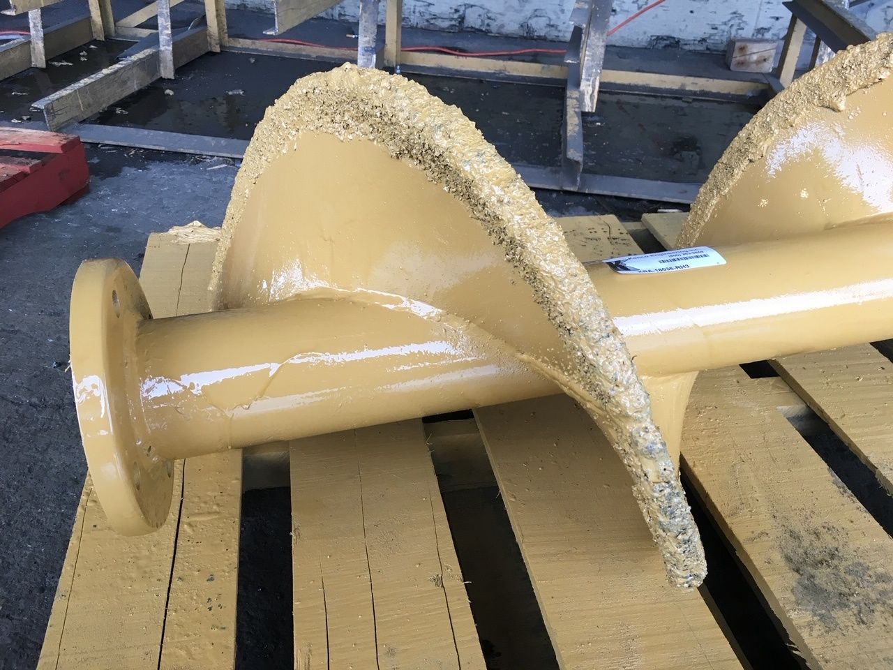
This photo shows the Kenco Engineering TCI steel strips installed on an auger.

Kenco Engineering Inc., Roseville, California, has been working to extend the life of augers for decades. At first, we developed the cast, bolt-on, auger shoe. This shoe incorporated a “lip” that wrapped over the outer edge of the auger to prevent the most common type of auger wear—diameter shrinkage.

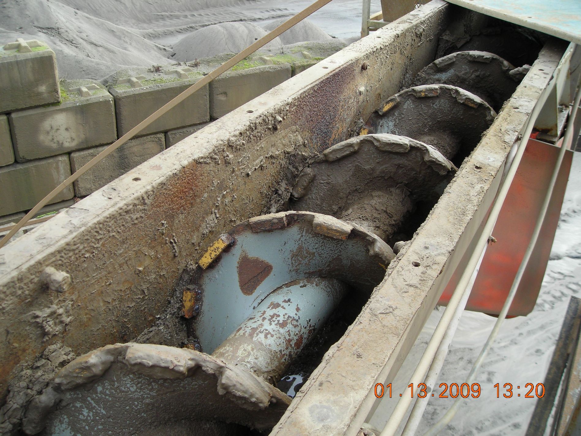
In many cases, an auger running in an abrasive material will wear from the outer edge toward the shaft, thus reducing the diameter of the auger, more than on the face of the auger. This diameter shrinkage dramatically reduces efficiency of the auger and its ability to transfer material.

Over the last few years, however, we have learned that using our Tungsten Carbide Impregnation (TCI) process to protect augers can perform even better than the cast shoe around asphalt plants, especially the dust fines reject auger.

This photo shows a fines reject auger that, for many years, had averaged losing 1 inch of diameter per month. This photo was taken at five years of service with no loss of diameter during that period.

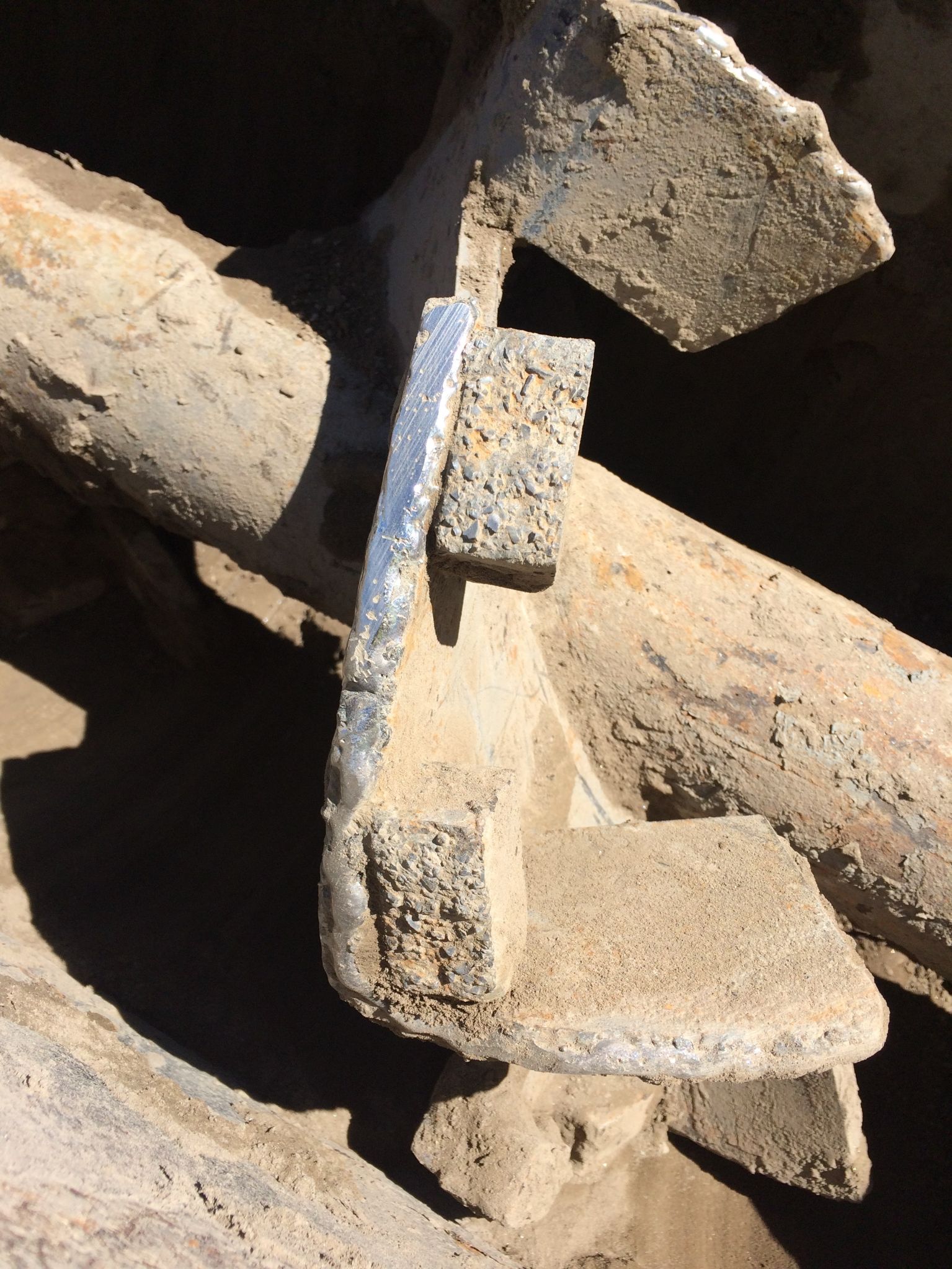
This next photo shows the use of our TCI bars on a “cut and folded” style dust auger. This customer had been changing out this auger half-way through each season. This photo was taken in the third season and the auger is still going strong.

The exceptional wear life of our TCI products comes from multiple factors. First is the hardness. At 90 Rockwell A, the hardness of Tungsten Carbide inherently makes it more wear resistant than even the hardest of AR steels. Next, with the rough texture of our TCI product, it traps material and helps create the cheapest of all wear products, material on material.

The versatility of our TCI product also enhances its usefulness around an asphalt plant. These two photos show the use of wear strips where Kenco impregnates our TCI into mild steel strips. These strips are then cut to size by the plant mechanic for installation on the auger or anywhere else wear is an issue. Due to their mild steel base, these strips can be welded with most common wire or electrodes for easy installation. As a final option, Kenco can manufacture a completely new auger with TCI protecting the outer radius as well as some portion of the face.

For more information on TCI protection, contact Brian Handshoe at brian@kencoengineering.com or visit www.kencoengineering.com.

9. Stansteel Tracks Your Trunnion Adjustment

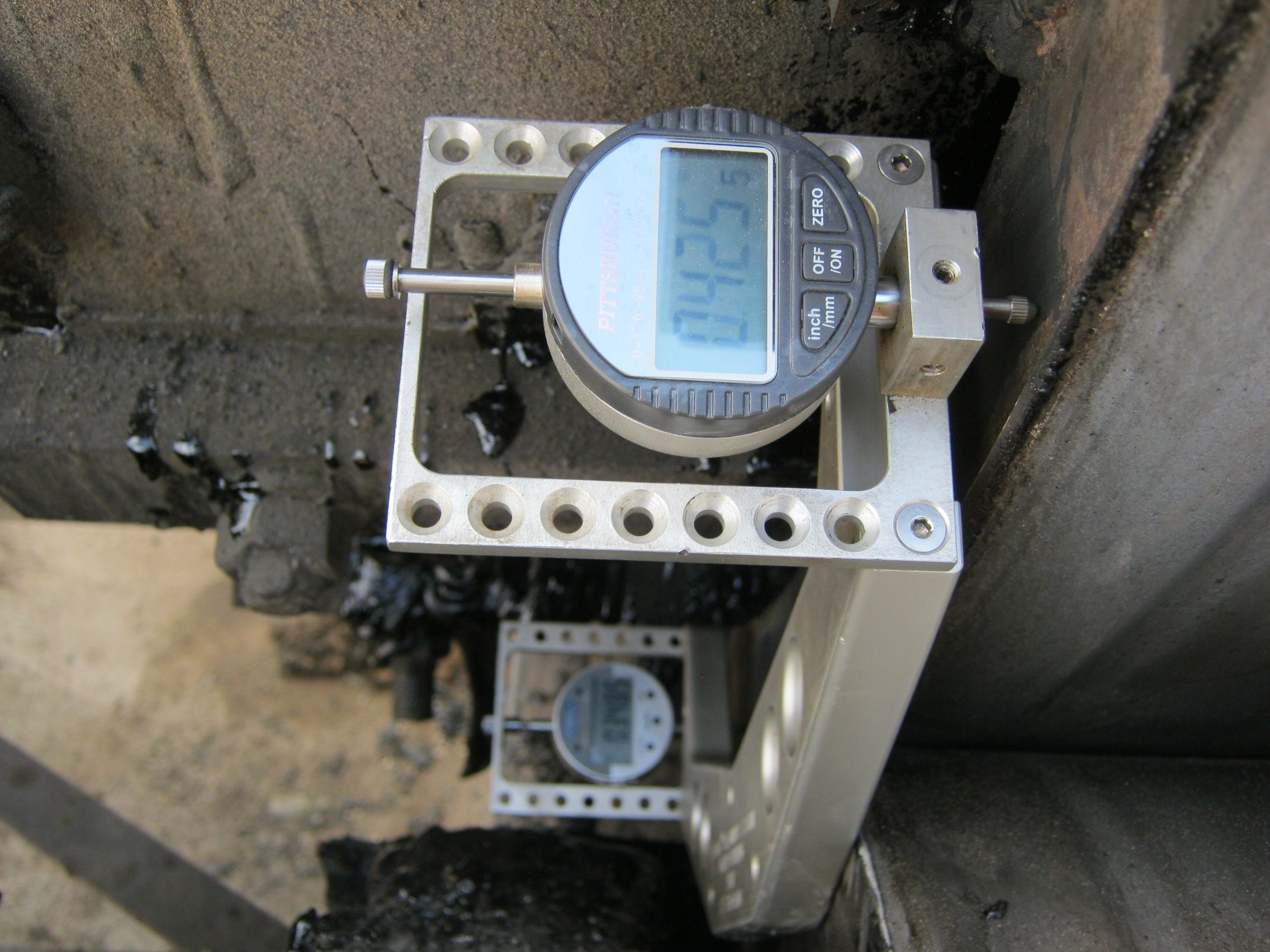
Depending on what stage of the adjustment process you’re in, you may want to see the numbers on the front and back displays be the same so the drum is not running uphill or downhill. Photo courtesy of Stansteel/Hotmix Parts & Service

Correctly adjusted trunnions reduce maintenance cost and plant downtime. Incorrectly adjusted trunnions cause a significant amount of abnormal wear and a multitude of premature failures that include broken thrust rollers, uneven tires and trunnions, and failed bearings. Precision adjusted trunnions maintain the plant’s tires and trunnions throughout the life of the drum and/or dryer.

There are many methods to adjusting trunnions. One common method is the use of a laser level and tape measure or other measuring device. This method is simple but not precise. While the laser beam is accurate, the width of the laser beam is not. Another attempt to keep trunnions properly aligned and skewed is to provide a measuring display on each trunnion base, but even this is not precise enough to prevent failures. The most precise and efficient method we’ve found for adjusting trunnions is our T-Trac Trunnion Alignment Tool by Stansteel and Hotmix Parts & Service. The T-Trac allows you to square the trunnions and tires within 100/1000th of an inch in precision.

In order to use the T-Trac correctly, lockout procedures need to be observed while working in contact with the equipment.

Once locked out and guards removed, the sides of the trunnions and tires need to be cleaned from dirt and grease.

The T-Trac consists of a magnetic base with dial indicators attached on each end facing the tire. Calibrate the dial indicators to the base with the included calibration blocks and the T-Trac is ready for use. Place the T-Trac on the side of the trunnion with both dial indicators on the side of the tire. Each of the four trunnions must be adjusted to the neutral position, meaning there is no longer uphill- or downhill-thrust. Adjust the trunnions to achieve a neutral (zero) delta between the two indicators, meaning that the trunnion is perfectly parallel with the tire.

The same method is performed for all four trunnions. Once all four trunnions are in a neutral thrust, the T-Trac can be used to skew each trunnion for the correct skew and thrust.

The trunnion adjustment methods of using a laser can take up to four to five hours to properly adjust your system. When using the T-Trac, precisely adjusting trunnions and tires can take as little as an hour and a half to complete the process for all four trunnions. The Stansteel & Hotmix Parts service technicians can visit your plant and demonstrate the T-Trac and adjust and skew your trunnions for you, ensuring precision accuracy of the adjustments.

For more information, visit stansteel.com.

Butler-Justice Inc.’s Blue Smoke Control System

Blue Smoke Control, a division of Butler-Justice Inc., Anaheim, California, offers two systems that, between them, are designed to eliminate emissions issues at the plant. According to Mike Butler, president of Butler-Justice, “The addition of RAP, rubberized asphalt and polymer blends into asphalt mix designs has led to higher emissions due to higher mix temperatures.” His company now provides environmental control devices that can be installed at the asphalt plant to remove up to 99.9 percent of blue smoke, as well as the odors associated with asphalt production. Here’s how:

The Blue Smoke Control system captures blue smoke from emission points in the asphalt production process.

Because blue smoke is essentially vaporized oil at high temperatures, Blue Smoke Control’s ducting system bleeds ambient (outside) air at key points. Seven stages of filters help to coalesce the tiny oil vapor droplets and aerosols into larger droplets that can be filtered out by the blue smoke collector. The oil droplets drain from the filters via gravity to a collecting sump.

In some cases, the system can pull as much as five gallons of oil per day from conveyor transfer points, silo-filling spots, and truck load-out areas. Not only is the final high-efficiency filter 95 percent efficient at capturing particles as small as 0.3 microns (creating a filter that is equivalent to HEPA quality), the complete system is 99.9 percent efficient overall, according to the manufacturer.

In addition, the company offers its X-VOCS system, which features proprietary carbon absorption technology designed to filter and remove up to 99 percent of odors and VOCs, such as Hydrogen Sulfide (H2S), from the hot asphalt storage tanks. The X-VOCS incorporates a five-stage filtration system. In the first three stages, a series of filters remove more than 95 percent of targeted particulates down to 0.3 microns. In the final two stages, carbon filtration beds remove remaining odors and volatiles.

When the X-VOCS technology is coupled with the Blue Smoke Control system, emissions from HMA plants can be reduced to nearly zero, providing owners with the means to achieve the highest level of environmental stewardship. Implementation of this technology has been proven to virtually end calls from nearby neighbors regarding odor and visual emissions. Both the Blue Smoke Control and X-VOCS systems can be incorporated into new plant designs, and they are also easily retrofitted into existing plant operations, with minimal modifications to the plant.

For more information on the X-VOCS system, visit the Blue Smoke Controls website.

How to Dispose of Silica Dust

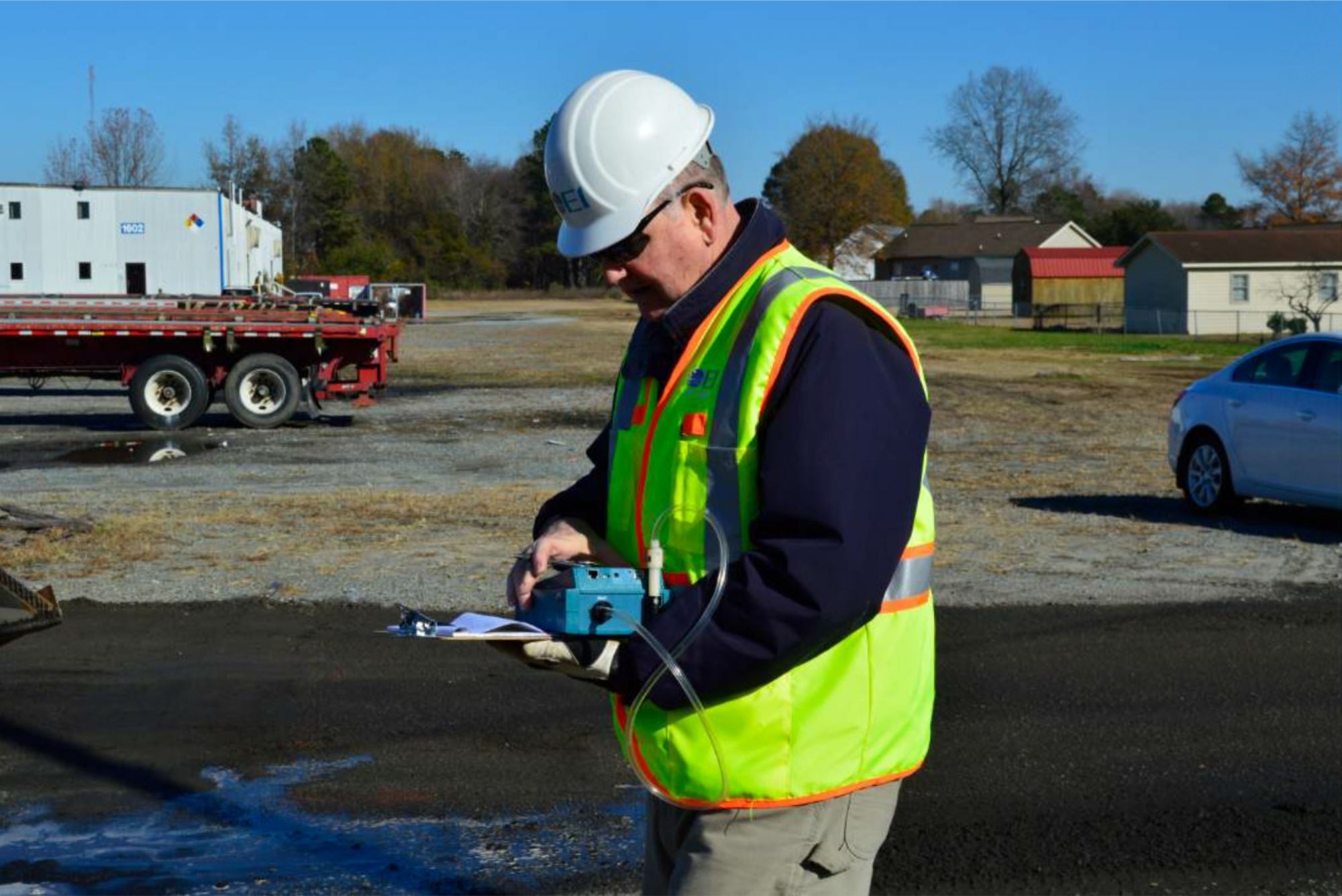
An estimated 2 million construction workers in the United States have been exposed to respirable silica dust, according to the Occupational Safety and Health Administration. That’s why OSHA’s Respirable Crystalline Silica standard requires that employers limit workers’ exposure to silica and take other steps to protect workers.

“Silica dust appears in asphalt, concrete and rocks,” said David Rigsbee, CEO at Chemtek Inc., Morrisville, North Carolina. “Any activity that involves breaking, cutting, demolishing, grinding, etc. of those elements will create silica dust.” That means many activities in our industry have the potential to create respirable crystalline silica dust that can be inhaled by nearby workers.

The standard (29 CFR 1926.1153) requires employers to limit its workers’ exposure to and provide protection from silica dust. Employers have the option of following a control method laid out in Table 1 of the construction standard or they can measure workers’ exposure and decide which dust control methods will reduce workers’ exposure to the permissible exposure limit (PEL).

Check out AsphaltPro’s article, New NIOSH Software Measures Silica Exposure FAST, for more information about measuring respirable crystalline silica levels.

How Silica Dust is Collected

According to OSHA, the main types of engineering controls for silica are wet methods and local exhaust ventilation.

Wet methods involve applying water or foam where the dust is generated to prevent it from getting into the air, whereas local exhaust ventilation removes dust by capturing it where it is created.

For example, a grinder, walk-behind milling machine or jackhammer must be operated with either a water delivery system or a shroud and vacuum dust collection system.

If using water to suppress dust, you must ensure an adequate supply of water, hoses are intact, and that the spray nozzle is working and pointed at the point of dust generation. OSHA’s Small Entity Compliance Guide for the Standard for Respirable Crystalline Silica for Construction doesn’t dictate a minimum flow rate, but states that the equipment must apply water at the flow rate specified by the manufacturer.

If using a dust collection system, it must have a filter with 99 percent or greater efficiency and a filter cleaning mechanism, and it must be able to maintain the air flow recommended by the manufacturer. On the job, be sure to check that the shroud is intact and properly installed, the hose connecting the tool to the vacuum is intact without any kinks, the filter is cleaned or changed to prevent clogging, and bags are regularly emptied to avoid overfilling.

Silica Collection for Milling

Within the world of asphalt, Rigsbee said, the lion’s share of silica dust comes from sweeping and milling operations. The most common containment method for sweeping and milling, Rigsbee said, is spraying water onto the dust. However, after OSHA passed 29 CFR 1926.1153 in 2017, reducing the amount of dust allowed from 250 micrograms per cubic foot to 50, water alone may no longer be sufficient to suppress silica dust to the standard.

“To give you an idea, if you have more dust onsite than the size of Abraham Lincoln’s forehead on a penny, you are now over the limit and could be fined by OSHA for tens of thousands of dollars,” Rigsbee said.

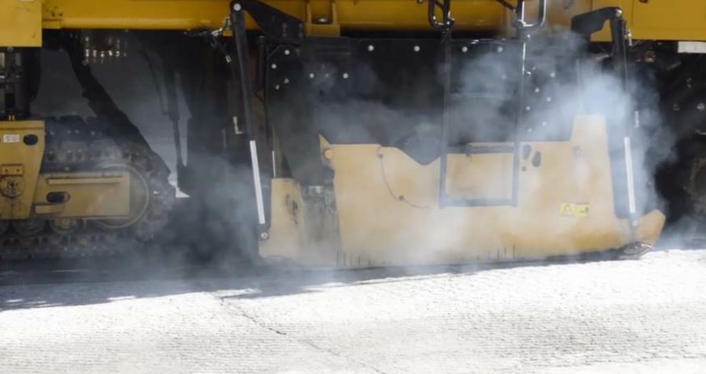
That dust is also hydrophobic, meaning it fails to mix with water. Pair that with the stricter requirements, and even contractors using wet method can struggle to contain silica dust. To combat this, some companies choose to add a silica dust suppressant, such as Chemek’s NeSilex, to the water to break down the barrier between the dust and water.

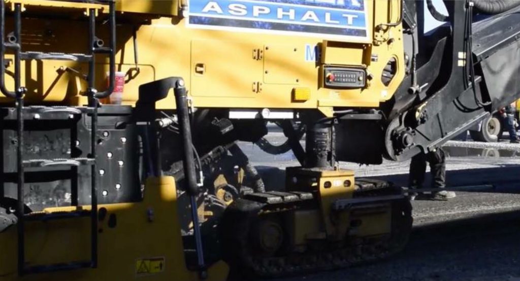
According to Steve Howard, safety and facilities manager at Wirtgen America, Antioch, Tennessee, its milling machines use water and a vacuum system to control dust. The vacuum system captures dust particles from the cutter house, transports them through a hose, and ejects them out the end of the conveyor.

Silica dust suppressants, such as Chemtek’s NeSilex, break down the barrier between dust and water to aid in silica control. These photos show the milling process with (above) and without (below) NeSilex. Photos courtesy Chemtek Inc.

Wirtgen was a part of the Silica/Asphalt Milling Machine Partnership, which was comprised of the National Asphalt Pavement Association, manufacturers, labor, academia and the National Institute for Occupational Safety and Health (NIOSH). The partnership “worked to design, test and implement engineering controls for milling machines that effectively reduce potential silica exposure below OSHA’s new proposed permissible exposure limit,” according to NAPA’s website.

“During those tests, we realized that water was a good method and the vacuum system was also good, but baghouses were not proven to be effective,” Howard said. “Baghouses work at an asphalt plant, but they are more equipped for that at a stationary plant. Not only would there be a whole big attachment on the milling machine, but also someone would have to get rid of that material at the end of the day and risk exposure then.”

“All milling machine manufacturers currently offer/use water and dust extraction on their milling machines,” said Matt White, North American Sales Manager for Milling and RS at BOMAG, Ridgeway, S.C. However, the vacuum system transfers the dust, versus reducing it, he added. “Transferring the silica dust is enough to meet today’s standard and ensure the operator isn’t exposed to it.”

White said that recent tests performed by BOMAG have indicated that dust particles could remain in the air on the job site for up to 40 hours after the milling machine has passed. That’s why BOMAG has developed its Ion Dust Shield for its 4-foot class machine.

According to White, the system reduces the PM 2.5 and PM 10 sized particles creating during the milling process by at least 80 percent.

“The system removes this dust by clumping or sticking it together by positively charging the particles,” White said. “This particle size is respirable dust that goes directly into the lungs and bloodstream, and is not seen by the naked eye.”

BOMAG plans to showcase its Ion Dust Shield in the American market in the fall of this year. The system is already available on milling machines sold in Europe.

“We’re preparing for the direction we’re headed,” White said. “Regulatory agencies aren’t going to make the standards any less stringent.”

Regardless of the system you employ, Howard reiterates that it’s imperative to use the vacuum system while milling.

“The employer has to make sure they use and maintain the system correctly,” Howard said. “If you have the system, you should use the system. If it breaks, you need to get it fixed.”

Silica Collection for Sweeping

“Most operations don’t create that much uncontrolled really fine dust,” said Brian Giles, product manager at Schwarze Industries, Huntsville, Alabama. What does create a good amount of the troublesome fugitive fines is equipment driving on top of larger particles, such as sand and powders and crushing them into dust. “The best role for the sweeper to play is to remove those larger particles to prevent from getting crushed into fine particles.”

Giles said the key to control fines generation is keeping the area clean. Once the particles become dust, he added, there’s only so much a sweeper can do.

“Catching the fine stuff is almost like catching smoke,” he said. Giles estimates a sweeper can’t efficiently control anything smaller than a PM 10, as it becomes airborne when anything comes close to it.

That’s where the wet dust control method is integral, to cluster those fine particles into larger particles that the sweeper can pick up and reduce any fugitive emissions from the sweeper.

For open air activities that generate dust, such as pavement milling operations, Giles said wetting down those particles is a must. If the sweeper follows closely enough behind the mill that is using adequate water, Giles said it may not need to use its own water to suppress the dust, though that is always an option if needed.

Micro milling, Giles said, is another game entirely. “Regular milling makes chunks, not powder,” he said. However, Giles compares the wetted down dust behind a micro mill to soupy black snow. For that, he recommends a vacuuming process along with traditional sweeping.

According to page 43 of OSHA’s compliance guide, slurry generated by wet methods should be cleaned up before it dries using a wet vacuum.

Vacuum manufacturers’ operator manuals typically provide instructions for changing dust bags and filters. For example, Rigsbee said, this could involve disposing of dust bags and filters in sealed, impermeable containers, such as heavy-gauge plastic bags, to prevent the release of dust particles into the air.

OSHA’s compliance guide states never to sweep or use compressed air on dried slurry. If slurry dries, they instruct immediately wetting it down and cleaning it up with a wet vacuum.

Some states may have more specific requirements for disposing of silica dust, so it’s best to contact your state Department of Environmental Protection or your regional office of the Federal Environmental Protection Agency for more information.


Dispose of Dust Collection Bags

If using dust collection as a method to protect workers from respirable crystalline silica dust, changing out the dust collection bags is inevitable.

According to Eric Massinon, business development manager at Chicago Pneumatic Power Technique, one bag can last for an entire day on the job before requiring replacement, depending on the media being worked.

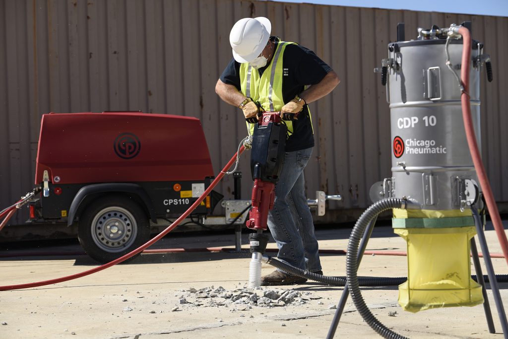
In January of this year, Chicago Pneumatic released its new CDP 10 dust collection system kit to help protect workers from exposure to crystalline silica during common construction tasks. The kit includes a vacuum suction unit, 21-foot suction hose, universal shroud connector, three dust collection bags and three bellows.

For the CDP 10 dust collection system, the bags should be changed when filled to 25 percent (2 to 3 inches full). The bags allow visibility to see the level of dust inside of them.

The bags should be sealed and disposed of properly following local applicable environmental legislations for disposing of silica dust, CP said. As seen in the photo within this sidebar, a belt will tighten around the top of the bag to seal it in place.

The CDP 10 comes with three bags, and additional bags and filters can be purchased at any dealer for CP.

The filters used on the CDP 10, which has the capacity of 99.58 percent filtration of exhaust air, can and should be washed out and reused, CP said, adding that they should be replaced after a couple of cleanings. A vacuum indicator notifies the operator of a clogged filter. CP reminds us that operators should wear dust masks any time they are exposed to respirable crystalline silica dust.

CP released its new CDP 10 dust collection system kit to help protect workers from exposure to crystalline silica during common construction tasks.

Use Low NOx Burners to Decrease Emissions

It may sound like a contradiction to use combustion to lower emissions, but industry has both smart operations and ever-advancing technology to reach the goal of more environmentally friendly output. From training your plant operator on best practices to tuning your existing burner for optimum efficiency for your specific production capacity to installing newly designed burners, you have options to ensure your asphalt plant meets nitrous oxide (NOx) emissions regulations in even low-attainment areas.

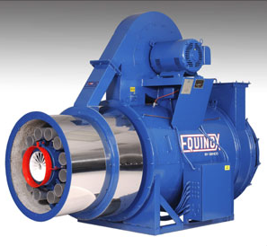
The EQUINOX™ burner from Genco is completely pre-assembled on a steel unitized frame. Photo courtesy Genco.

The EQUINOX™ burner from Genco is completely pre-assembled on a steel unitized frame. Photo courtesy Genco.

Check on Technology

Industry and entrepreneurs were concerned with NOx reduction back in 1977 when the John Zink Company applied for U.S. Patent No. 4,004,875 to develop a low-NOx burner. A year and a half later, Robert Reed filed for a related invention patent. He wished to design a burner to control the fuel and air supply within the burner “such as to maintain a minimum value of NOx in the effluent gases” no matter the fluctuations in burning rate or air supply rate.

By Aug. 30, 2000, Gencor Industries Inc., Orlando, filed a patent for the low emissions burner with premix flame stabilized by a diffusion flame. Now Genco, under the Gencor umbrella of companies, offers the EQUINOX™ combustion system, which is designed to reduce the use of flue gas recirculation, by a primary stage pre-mix accumulator and a second stage, patented injection system. The company states that this results in a stable combustion flame with little to no effect on the exhaust system of the process.

Early in the 2000s, Hauck Manufacturing Company worked with patents for a number of lean premix burners and three-stage burners. Paul Lavenberg, a spokesperson for Honeywell Thermal Solutions, Rockford, Illinois, which now owns and manufactures the Hauck brand, listed the following current patents.

  • Hauck NovaStar Burner: US20140308619, US8113821
  • Hauck EcoStar II and MegaStar Burners: 5700143
  • Hauck EcoStar II, MegaStar and StarJet Burners: US6969249

Astec Industries, Chattanooga, offers the Phoenix® family of burners to mix the air and gaseous fuel for a low NOx and CO method called lean burn premix. Its ultralow-NOx burners “employ a multiple, parallel, turbulent, tube mixer to achieve near perfect mixing of fuel and air.” Running in lean burn mode allows a compact flame size, which the company states, “contributes to efficiency, ensuring that all of the fuel is combusted without taking away valuable heating capacity.”

It is evident that low-NOx burners—and ultralow-NOx burners—available for use in the asphalt industry have a solid family tree. Asphalt industry members remain on the cutting edge of environmental sustainability, working to keep actual emissions, and the implication of emissions, to a minimum.

GreenGlobes.com tells us, “When fossil fuels are burned, nitric oxide and nitrogen dioxide are produced.” The site also explains: “The nitrous oxides (NOx) come from two sources: high-temperature combustion (thermal NOx) and nitrogen bound to the fuel (fuel NOx). For clean-burning fuels like natural gas, fuel NOx generation is insignificant.”

For this reason, and others, researchers and developers wish to reduce flame temperature, and environmental groups wish to ensure everyone who uses a burner for any purpose uses a clean-burning fuel in the most efficient combustion process possible. The many patents filed, and alluded to above, to create low-NOx burners for a variety of industries focused on creating a “fuel-rich combustion zone” ahead of a “fuel-lean combustion zone.”

Lennie Loesch, the president and CEO of Stansteel/Hotmix Parts & Services™, Louisville, Kentucky, discussed efficient combustion and fuels. “Basically, NOx is formed at extremely high temperatures, over 2,800oF. This high temperature certainly occurs when you have a hotter burning fuel such as recycled fuel oil, waste oil and other items like that. For all practical purposes, about the only fuel that can be used, if you’re trying to get a low NOx level, is natural gas or propane.

“Because the bonding of the hydrocarbons and emissions happens over this high temperature,” Loesch continued, burner developers have sought ways to cool down the flame. “That can be done by quenching with air or recycled flue gas to bring back some of the gases that already have the oxygen out of them, to help supply a cooling air or cooling gas for the main primary combustion.”

Loesch mentioned the one-time popular idea of spraying water on the combustion air. “The water, of course, creates the need for more energy. Even though it may accomplish lower NOx, it’s at the tremendous cost of fuel efficiency.”

Honeywell’s Lavenberg discussed other ways technology can step in to help. “With some ultra low-NOx burners, pre-mixing the air and gas at certain air to fuel ratios allows for considerable flame temperature reduction and very effective NOx reduction. The use of ‘excess air’ allows this technology to work. Excess air is the use of additional air above and beyond the amount of air needed for perfect combustion to reduce flame temperatures.”

Lavenberg provided a list of ways flame temperatures can be mitigated:

  1. Water injection
  2. Fuel staging—prolongs and delays mixing of fuel and air, thereby reducing peak flame temperature. Fuel is introduced in “stages,” rather than one single point.
  3. Combustion air staging—prolongs and delays mixing of fuel and air, thereby reducing peak flame temperature. Air is introduced in “stages,” rather than one single point.
  4. Internal flue gas recirculation—fuel and air mixing turbulence recirculates products of combustion back into the flame causing reduced flame temperatures.
  5. External flue gas recirculation—a portion of the burner exhaust is reintroduced into the burner to reduce the oxygen content in the combustion air thereby reducing the flame temperature.

As of press time, only a handful of states require asphalt plants use a low-NOx burner for operation. California, New Jersey, New York and South Carolina have this on the books.

“Areas of non-attainment may have local air quality requirements that impact asphalt plants,” Lavenberg explained. “Contractors who are anticipating emissions regulations may be proactive in selecting a low-NOx burner for their plant. This can be risky if the proposed or actual regulations require lower emissions than certain burners are capable of.”

An example in New York gives some insight regarding the low-NOx justification in the environmental mindset, and offers a couple ideas for producers.

The New York State Department of Environmental Conservation (NYSDEC) issued a permit under the Environmental Conservation Law (ECL) to Gernatt Asphalt Products Inc., Collins, New York, for its Westfield Asphalt Paving Plant in Westfield, New York, June 1, 2011. That permit has no expiration date, but does allow inspections at “reasonable” intervals. The permit holder must follow a number of rules at all times or the department can modify the permit, suspend it, or flat out revoke it at any time.

“The grounds for modification, suspension or revocation include…Exceeding the scope of the project as described in the permit application; Newly discovered material information or a material change in environmental conditions, relevant technology or applicable law or regulations since the issuance of the existing permit….”

These conditions mean the owner of the Westfield plant must keep the facility operating in its original capacity within the DEC guidelines. It was permitted in 2011 with a 400 ton per hour production capacity. According to the permit, the dryer included a 100 mm BTU per hour low-NOx natural gas burner. The drum exhaust vented to a pulse jet baghouse with 70,000 ACFM. The permit includes a “federally enforceable emission cap that limits asphaltic concrete production to 450,000 tons during every 12 month period.”

The permit has a few other dictates, which offer a couple of best practices ideas. “As per 6NYCRR Part 212.12, this permit includes: (1) the requirement to complete an annual tune-up on the dryer burner, (2) a performance test of the dryer burner to demonstrate the burner is a low NOx burner, and (3) a plan which details methods to reduce the moisture content of the aggregate piles.”

Just this year, Honeywell Thermal Solutions supplied two MegaStar burners, which are conventional low-NOx burners, to a contractor in New York. Photo courtesy Honeywell Thermal Solutions.

Just this year, Honeywell Thermal Solutions supplied two MegaStar burners, which are conventional low-NOx burners, to a contractor in New York. Photo courtesy Honeywell Thermal Solutions.

Apply Your Knowledge

Tuning the burner on a regular basis and managing stockpiles to reduce moisture remain best practices for the asphalt producer, whether his facility is in a low-attainment area or not.

“The producer makes a huge mistake if he doesn’t have the burner adjusted and tuned by a qualified technician at least once per year,” Loesch said. “It is mandatory if different types of fuels are used because the air system, flighting and many other factors will affect not only the emissions, but also dramatically change the burning efficiency and fuel cost.”

Other best practices include training operators for optimum efficiency.

“First thing in the morning, you light up everything and put the burner on low heat,” A.J. Ronyak advised. He’s the proprietor of Odor Solutions Group and an asphalt production consultant. “Run the drum and conveyor belts dry on low heat for 30 minutes to an hour, depending on the time of the year, to warm up the baghouse and get the dew out. Then when you’re ready to start production, you’ve already created that hot air environment.”

One of the ways to optimize your burner use is to concentrate on moisture reduction before material even gets to the dryer. You’ve sloped and paved beneath the stockpiles; the RAP piles are covered to keep rainwater out. But humidity and moisture still sneak in. Companies like Ray-Tech Infrared Corp., Charlestown, New Hampshire, offer heating solutions ahead of the dryer to help reduce moisture significantly. “Then you can concentrate your heat on your aggregate and don’t have to worry about the RAP,” Ronyak said. What he suggested is to watch each material coming in. “Don’t try to conserve on the AC temperature. If you heat up the liquid AC, you can throttle back on the burner, and the guys on the street will still get their 300-degree mix to work with.”

These precise maneuvers require the plant operator to have confidence in his equipment. Honeywell’s Lavenberg pointed to the controls systems available in the industry to help operators. Plant controls can do so much more than blend mix these days.

“Often, advanced burner controls play a significant role in helping burners achieve precise, repeatable air-fuel ratio control, which contributes to NOx reduction,” Lavenberg shared.

Prior to shipment, each burner is tested on one of Astec’s tri-fuel (oil, gas & liquid propane) test stands to ensure fast and easy start-up at installation. This is the Phoenix® Phantom low-NOx burner. Photo courtesy Astec.

Prior to shipment, each burner is tested on one of Astec’s tri-fuel (oil, gas & liquid propane) test stands to ensure fast and easy start-up at installation. This is the Phoenix® Phantom low-NOx burner. Photo courtesy Astec.

Loesch concurred. “New control systems…can be retrofitted to virtually any burner and will automatically adjust the air and fuel ratio by individual control modules.”

When you’re ready to make the upgrade to a low-NOx burner, it’s not as simple as switching out the burner and turning everything back on. As Loesch mentioned earlier, recycled fuels are no longer appropriate. Lavenberg explained that gaseous fuels are most suitable for use with low-NOx burners. This means you will need a source for natural gas or propane. Lavenberg listed some other things to consider:

  1. Combustion zone sizing in the dryer is important so the flame can fully develop without aggregate falling through the flame.
  2. Proper exhaust draft control—the exhaust system must be able to pull the products of combustion out of the dryer and allow for reasonable draft under production conditions.
  3. Be aware of possible contamination of aggregate from blasting compounds that contain nitrogen. In addition, materials may have agricultural runoff containing nitrogen as well.
  4. Precise air to fuel ratio control—use of electronic air/fuel biasing allows for precise control of air to fuel ratios.

State regulations may not require an upheaval of technology in your neck of the woods just yet. While you watch for new rules, keep the best practices mentioned above in mind to reduce your already low stack emissions now, and get prepped for just-in-case installation of a low-NOx burner in the future.

As of press time, only a handful of states require asphalt plants use a low-NOx burner for operation. California, New Jersey, New York and South Carolina, for example, have this on the books.


Clean Diesel Reduces Emissions

The success of private industry, government, environmental and health organizations in working to replace older diesel engines with near-zero emission clean diesel technology has reaped significant air quality improvements in the Midwest and throughout the United States, according to the Diesel Technology Forum.

In a presentation to the Midwest Clean Diesel Initiative (MCDI) in Chicago Oct. 26, Ezra Finkin, the director of policy for the Diesel Technology Forum, highlighted several of the clean air and health gains achieved over the past decade in reducing emissions from older diesel equipment.

The MCDI is a collaboration of federal, state and local agencies, along with communities, non-profit organizations and private companies all working together to reduce diesel emissions in Illinois, Indiana, Michigan, Minnesota, Ohio, and Wisconsin and 35 tribal nations.

Finkin outlined how new clean diesel heavy duty trucks (Model Year 2010 or newer) with near-zero emission have significantly reduced emissions by:

  • Eliminating 7.5 million tonnes of NOx
  • Eliminating 39 million tonnes of CO2
  • And saving 2.9 billion gallons of diesel fuel (65 million barrels of oil)

Source: Diesel Technology Forum