Burner Technology Trends in Asphalt Plants: What’s Driving Innovation in 2025

For the May edition of AsphaltPro Magazine, our product gallery focuses on the hot-mix asphalt plant (HMA), warm-mix asphalt (WMA) plant, aggregates management, and other asphalt mix production products and services. One of the components integral to the asphalt facility is, of course, the industrial combustion system. Since 1998, I’ve covered original equipment manufacturer (OEM) advancements in research and development of burners that offer lower and lower emissions opportunities.

The Hades burner is also available from Tarmac International as a LoNox offering and was on display at the Tarmac booth during WOA. For more information, visit https://tarmacinc.com/

SEO Executive Ganesh Dukare of Persistence Market Research, Brentford, London, offered some forward-looking statistics for the industry, stating: “The industrial burner market is expected to grow from US$ 6.4 billion in 2024 to US$ 9.18 billion by 2031, with a CAGR of 5.2%. Growth is driven by industrialization, mining and petrochemical activities, while leading companies are investing in advanced burner technologies to reduce pollution and carbon footprints.”

This is the Detroit® HADES-125 (125 MBtu/hr) Low Emissions, Long Nose Burner Firing Recycled Fuel Oil (Natural Gas Capable). Installed on a Herman Grant 400 TPH counterflow dryer at David A. Bramble, Inc. in Wye Mills, Maryland. For more information, visit HADES Burners – Detroit Stoker Company

According to the company’s research, the top three trends driving growth in the next few years are a growing demand for energy efficiency and sustainability, the integration of automation and the Internet of Things (IoT) into burner management, and the shift toward multi-fuel burners, all of which we’ve seen happening in the asphalt industry. At the recent World of Asphalt (WOA) and AGG1 trade show in St. Louis, the team from Honeywell Industrial Automation, Houston, had the Honeywell Hauck Multi-fuel MegaStar burner on display in the booth directly across the aisle from AsphaltPro Magazine’s booth. One couldn’t walk the show floor without noticing the preponderance of evidence of our industry’s proactive stance on energy efficiency and sustainability, and there’s more on that concept in the WOA wrap-up coming in the June issue.
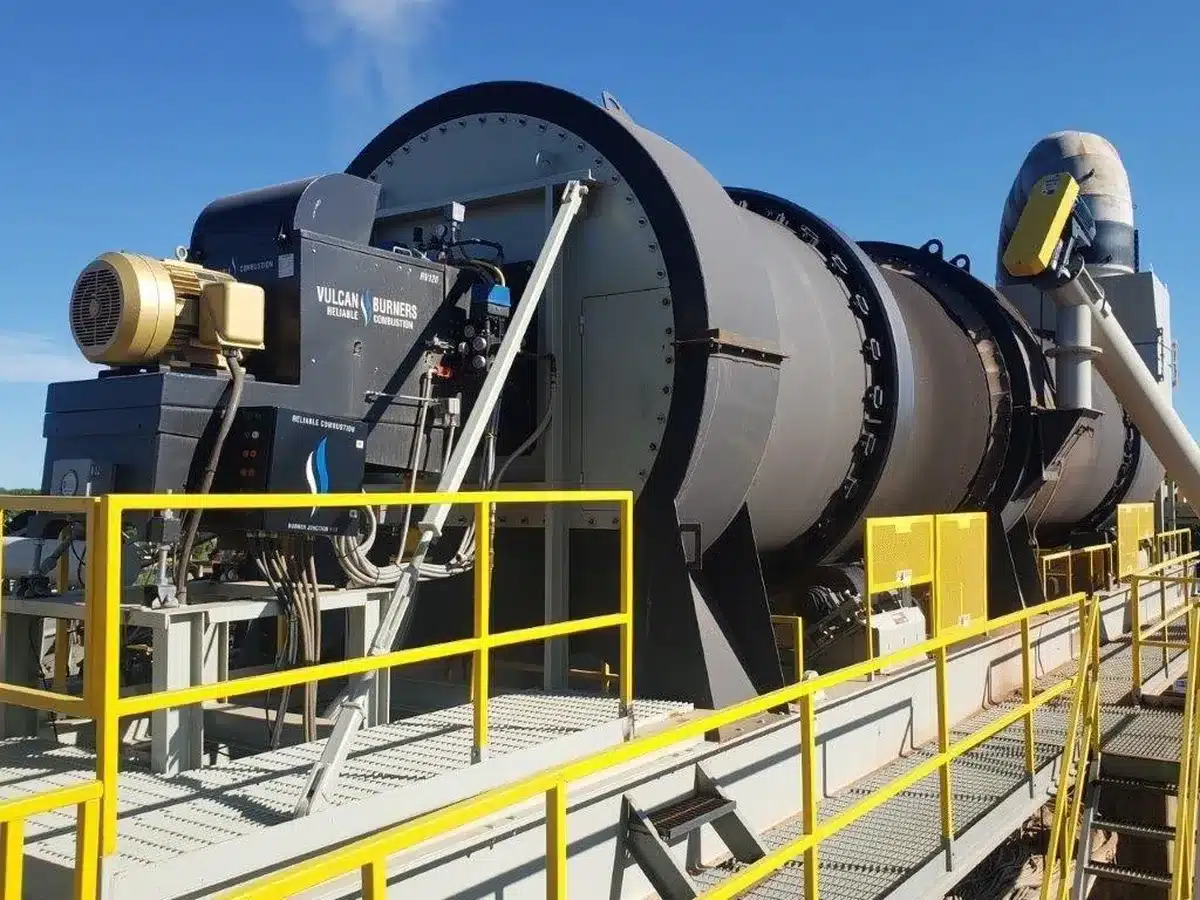
This is the RV120 long nose set up for natural gas and a single oil fuel. Currently running on natural gas. Located in Canton, Ohio. The Vulcan Burner is designed to accommodate various mounting configurations and plant layouts. Its low maintenance requirements stem from a direct-driven fan with no belts, coupled with a split housing design that facilitates easy access for servicing. The burner is capable of operating on multiple fuel sources and incorporates a comprehensive air system to enhance air control and overall efficiency. Safety is a priority, with features including an over-temperature switch and an additional switch to alarm when the housing is separated. Powered by a 75-horsepower motor, the direct drive axial fan delivers an air output comparable to larger motors while maintaining energy efficiency. The sound-insulated fan intake ensures quieter operation. Vulcan Burners are readily available. Replacement parts are also kept in stock for fast shipping. For more information, visit https://reliableasphalt.com/

Persistence Market’s research also shows the top three innovations in industrial burner technology are low emission burners, burners with smart combustion control systems and burners for renewable energy applications. One of the market opportunities they see for burner manufacturers is a focus on retrofit and upgrade solutions. As an example, the team at Meeker Equipment, Belleville, Pennsylvania, offers the Patriot-E electric hot oil heater, which is designed to fit into the footprint of a producer’s “former” combustion hot oil heater.

Examples of how the asphalt industry’s original equipment manufacturers (OEMs) provide systems in all the trending categories above abound. I can point directly to the Whisper Jet® LE burner from Astec Industries, Chattanooga, and the company’s Intelliflex burner controls on display at World of Asphalt as merely one in a robust and environmentally responsible industry of options. Let’s look specifically at what Persistence Market Research had to say about integrating automation and IoT into industrial burners. They began by acknowledging this integration is revolutionizing how these systems are managed and monitored.

The Whisper Jet® LE burner from Astec Industries, Chattanooga, is designed to cleanly and efficiently burn oil, natural gas or propane, and its compact flame makes it compatible with virtually all drum designs without complicated adjustments. Rapidly swirling high energy air is the key to the Whisper Jet burner’s combustion. The swirling air and flame are created by the fixed internal spin vanes and the patented castellated nose, ring and nozzle design. True to its name, the Whisper Jet burner is designed and equipped to reduce burner noise over competitive burners. For more information, visit https://www.astecindustries.com/products/details/whisper-jet-burner

“Modern industrial burners are now equipped with sensors and control systems that allow for real-time monitoring and adjustments. These IoT-enabled systems provide operators with valuable insights into burner performance, helping them detect inefficiencies, prevent malfunctions, and optimize performance.

“Furthermore, automated combustion control systems enable precise air-fuel ratio adjustments, enhancing combustion stability and efficiency. This integration not only improves operational efficiency but also reduces human error, leading to safer and more reliable operations. This trend toward automation and data-driven management is expected to continue as industries seek to improve productivity and reduce downtime.”

The MegaStar burner from Honeywell Hauck is designed to burn multiple fuels and was on display during World of Asphalt. For more information, visit https://process.honeywell.com/us/en/products

One aspect of burners we should focus on from the company’s research is that of the low-emission offerings. “These burners are designed to reduce the production of pollutants such as nitrogen oxides (NOx), carbon monoxide (CO) and particulate matter,” they wrote. “Low-emission burners are often equipped with advanced features such as staged combustion, flue gas recirculation and catalytic converters to achieve cleaner combustion. Innovations in burner technology, such as the use of advanced flame sensors and improved burner management systems, have made it easier to meet stricter emission standards while maintaining high efficiency. As governments around the world implement more stringent environmental regulations, the demand for low-emission industrial burners is expected to continue to rise.”

Watch for this department to feature more updates from WOA/AGG1 over the next few editions!

Check out the article from Malcolm Swanson of e5 Engineers, “Using Combustion Quality Management in Burner Emissions Control,” in the February 2025 issue for a detailed discussion of this technology and its application in our industry.

Using Combustion Quality Management in Burner Emissions Control

Persistence Market concluded their report stating, “The industrial burner market is evolving rapidly, driven by technological advancements, a growing focus on sustainability and the need for energy-efficient solutions. Innovations in low-emission burners, automation, multi-fuel burners and renewable energy applications are shaping the future of industrial combustion systems. With expanding markets in emerging economies and a growing emphasis on retrofitting older systems, the market holds promising growth opportunities.”

The plant-and-production product gallery following the successful WOA/AGG1 show would be remiss if it only focused on one component of the production process. Check out production iron and services in the next few pages from companies who exhibited at the industry event and companies who were unable to attend. Some of these products are new to the marketplace and some are tried and true technologies with upgrades to renew their efficacy for enhancing your bottom line. If there’s something that catches your eye, make sure you reach out to the OEM and let them know you saw it in the pages of your industry partner, AsphaltPro Magazine. And watch for this department to feature more updates from the recent show over the next few editions, as space allows.


ADM Unveils EX 8845 Asphalt Plant for High-Capacity Production

Astec Updates IntelliPac Moisture System for RAP Compatibility

CWMF Unveils Dust Pilot Baghouse for High-Capacity Asphalt Plants

Eagle Crusher Launches Next Gen 1200-CC Portable Crushing Plant at WOA

John Deere Adds Jobsite Monitoring Features to Operations Center

Lippmann Crushers Expands Midwest Reach With US Equipment Sales Partnership
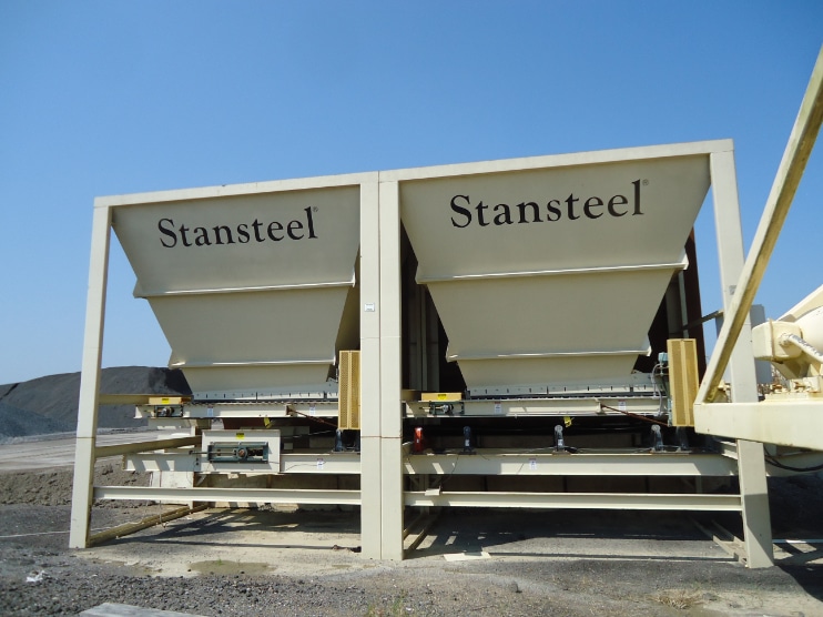
Assess the Feeds at Your HMA Plant

Here’s how to inspect the collecting scale and feed conveyors for RAP and virgin aggregate systems

Assessing components at the hot-mix asphalt (HMA) plant is only one step in the overall picture of plant health. The continuous drum mix plant has its best chance at optimum, clean production when all components and electronics are functioning properly without signs of wear or damage. If a duct, bin, flight, bag or other component develops a shiny surface, small leak or other problem, more than production suffers. Let’s continue this new series of assessing the asphalt plant for maintenance purposes with the reclaimed asphalt pavement (RAP) and aggregate feed components.

Step Up Hot-Mix Production with Your Facility’s Own Crushing Plant

Safety Notes

The first step with any plant maintenance is to make sure all inspections, markings or repairs happen while using proper OSHA Lockout/Tagout procedures. Ensure you have complete power disengagement before performing any inspections or repairs. For observations that require belts, idlers, motors or other components to be operating, listen or watch for vibration and noises from a safe distance or rely on controls systems to provide feedback on specific parameters. In this situation, you will observe and document, but do not touch the operating equipment.

For this series on assessing your asphalt plant for upcoming repairs and to avoid unplanned downtime, plant owners are reminded that only fully trained personnel should be allowed to conduct work on or around the equipment. For safety’s sake, the worker(s) should be fully trained on and act in accordance with all federal, state, county and local laws and regulations, and that includes OSHA and MSHA laws. You want your workers to be familiar with and act in accordance with the equipment specifications and manuals as well as your site-specific safety rules and regulations.

Workers have to take responsibility for their own actions, inactions, consequences and results, but you can ensure the best possible outcome for their safety and your operation’s success when you take the time to train and educate each worker who has access to the equipment and material at your facility.

Always use OSHA Confined Space procedures.

Fix a Torn Conveyor Belt

Feed Conveyor Belt

Starting with the collecting conveyor today, let’s inspect the collecting and feed conveyor belting. You want to perform a visual inspection of the entire unit to look for any noticeable issues. Make a note of all areas that are damaged and mark them for immediate repair or replacement. See “How to Fix a Torn Conveyor Belt” in the May 2020 issue for tips on repairing a worn or torn conveyor belt.

  • Check for cracks or dry rot
  • Check for rips or tears
  • Check for damaged seams
  • Check for proper (2-ply, 3-ply, etc) thickness
  • Check for signs of proper tracking
  • Inspect all rubber skirting for holes
  • Inspect all air lines for damage
  • Inspect all wiring/junction boxes/terminal strips
  • Check for any frayed, burned, broken, melted wires
  • Reinstall any guards that have been removed during inspection/repair
  • Check that the zero speed sensors operate correctly
  • Check that the load cells operate correctly
  • Check that tachometer zero speeds operate correctly

A well-maintained and properly functioning cold feed system is integral to the success of your plant. Keeping it in good working order keeps your operation safe as well as efficient.

Feed Conveyor Belt Scale

Moving on to the belt scale inspection, start with its calibration. You want to ensure it has been calibrated correctly for low, medium and high production. Make sure the test weights have been tested as well. Inspect the gravity take-up.

Make sure spare components for the belt scale are in stock since this is critical to the operation. Certainly, a load cell can fail for many reasons, and you should always have a back-up available.

Of special note: Please investigate advances or upgrades in electronics that can help fast daily belt scale calibration and verification since 100% of the blending and gradations of materials depend on proper belt scale function and matching to liquid additives—including liquid asphalt—chemical additives, dynamic foaming and more.

American Asphalt Serves Two Plants with One Footprint

Feed Conveyor Bearings

To inspect the bearings on the collecting/feed conveyor, look down. If you see signs of leaking oil or other signs of damage, your task may require a closer inspection.

  • Are the bearings properly lubricated?
  • Are their operating temperatures normal?
  • Is there visual abnormal coloration? (blackened grease)
  • Is there any excessive grease/oil escaping the bearings?
  • Are the bearing mounting bolts tight?
  • Has there been excessive vibration while in operation?
  • Has there been any excessive bearing noise while in operation?
  • Are there any cracks in bearing housings?

Eagle Crusher Company Displays UltraMax® 1600X-OC Portable Impactor Plant

Feed Conveyor Idlers

  • Do the idlers spin freely?
  • Are all idlers properly “string-lined” and aligned?
  • Is there excessive noise from idlers during operation?
  • Are all guards in place?
  • Are all idler brackets tight against the frame?

Feed Conveyor Drive Components

For the collecting/feed conveyor drive components, you’re looking at the motors, reducers, sprockets and guards. You want to ensure all motors are operating at normal temperatures and are properly ventilated. You also want to inspect the head shaft rubber lagging as well as the tail/wing pulley for wear. Any element showing signs of wear needs to be pointed out to the grounds crew or mechanic for repair.

  • Is there excessive noise/vibration during motor operation?
  • Have gearbox/motor oil samples been taken?
  • Are there any unusual odors from motors during operation?
  • Are all wiring connections tight? (you don’t want loose wires)
  • Are all motors connected to drive couplings.
  • Have you checked for proper oil levels in motors/reducers?
  • Are drive or drive sprockets showing signs of wear?
  • Are there any cracks in the shafts?
  • If applicable, are drive belts cracking?
  • Are sheaves showing signs of wear?
  • Are the drive couplings working properly?

If you have comments on any of the elements you’ve inspected, make those notes for your grounds crew or mechanic and set a date by which you’ll check back on the progress of repairs. A well-maintained and properly functioning cold feed system is integral to the success of your plant. Keeping it in good working order keeps your operation safe as well as efficient.

Adding Liquid Capacity Increases Flexibility for R.K. Hall

R.K. Hall and BROCK partner on enhancing performance for the plant


Editor’s Note: The new Focus on Performance series from AsphaltPro Magazine allows OEMs and service providers in the industry to highlight asphalt professionals who have improved efficiencies and the bottom line through best practices and performance. This month’s installment, featuring R.K. Hall, Paris, Texas, dives specifically into efficiencies gained through adding liquid asphalt capacity.

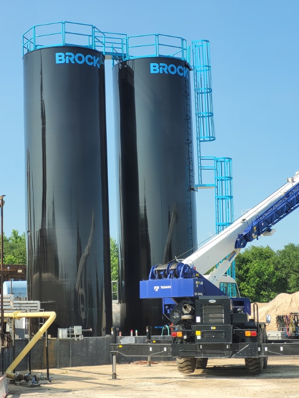
During 2024, R.K. Hall, a division of Summit Materials at press time, headquartered in Paris, Texas, increased capacity at two of its 11 asphalt plants by adding larger, vertical liquid asphalt cement (AC) tanks from BROCK LLC, Chattanooga. With more mix designs and projects on the horizon, the company will update additional sites with similar tanks over the winter and Manager-Asphalt Plants Richard Yates shared how this strategic plan benefits the producer.

“We use a lot more grades of asphalt than we used to, so some of this is a storage requirement.”—Richard Yates

In June 2024, R.K. Hall and BROCK worked together to install a new, 30,000-gallon, vertical AC tank at the Mt. Pleasant plant to increase liquid storage and give the site more flexibility. All photos courtesy of BROCK

Logistics

The two sites we’re discussing in this article are located in Mt. Pleasant and Denison, Texas. Both are facilities R.K. Hall acquired in 1992 and 2010 respectively and has been updating and upgrading as time allows.

The Mt. Pleasant site is about an hour and a half to two hours from the nearest refinery from which they draw liquid; the Denison site is about three hours away from the nearest refinery. While there are other refineries to draw from, those are the closest and require careful scheduling of material use and delivery when the site only has two or three storage tanks. The company is giving personnel like Justin Mulino, plant manager at Mt. Pleasant, some breathing room by setting up more tanks at a facility.

“We needed more storage,” Yates said. “Some of our facilities are relatively close to refineries and some are not. Having four, five, six tanks simplifies our lives. We use a lot more grades of asphalt than we used to, so some of this is a storage requirement.”

Performance grade (PG) 64 is a base grade used for many Texas Department of Transportation (TexDOT) projects, so it’s natural for R.K. Hall to have that on hand, but the company has found itself needing to stock a variety of other grades and products to meet a growing demand for its own crews and customers.

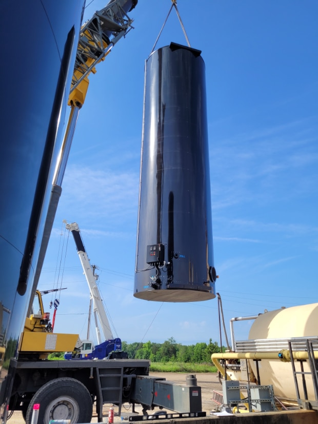
In these two images, you can see the delivery of a new 30,000-gallon liquid AC tank and its hoisting via crane at the Denison plant site. BROCK’s Lance Clark shared, “The entire R.K. Hall team is very professional, highly intelligent, and passionate about our industry.”

Pleasant

As of press time, the Mt. Pleasant site had five AC tanks—including the two 30,000-gallon vertical tanks they added from BROCK in June 2024—and was about to receive a sixth.

“It’s kind of an unusual marketplace,” Yates said. “We reach into Arkansas and sell to a lot of counties and cities that buy cold mix, so we have one tank dedicated to cold mix AC 1.5. We also do a lot of FOB sales to contractors doing TexDOT work needing different grades of oil. And if we’re doing a big project, we might need two tanks for that alone.”

That makes for a lot of moving pieces for Mulino to track, but Yates spoke confidently of the plant manager’s skills.

“It’s price-driven where we pull the oil from, and it might be three or four hours away. We average five transports a day coming in [with AC deliveries].” Add to that 30 to 40% of haul trucks for R.K. Hall and 60 to 70% for outside sales, and Mulino’s keeping it all coordinated.

“Justin started out as a ground man and has been an operator there at least five years now. He’s one of the more level-headed people I know. He can keep everything on an even keel. He’s calm, cool and collected most of the time. He’s calm in the face of the storm and when you’re running four or five jobs out of there, it can get pretty hectic. He’s able to manage it all.”

Lance Clark of BROCK also spoke of the team’s efficiency and partnership. “R.K. Hall has been instrumental in the growth of BROCK over the past four years,” Clark shared. “I have had the privilege of managing their account from day one. R.K. Hall provides constructive feedback on equipment designs, which we implement as design standards, to make products better for our customers. The entire R.K. Hall team is very professional, highly intelligent, and passionate about our industry.”

Denison and Beyond

The Denison site came with two 20,000-gallon horizontal tanks, to which the company added a 30,000-gallon vertical from BROCK in April 2024.

“We don’t buy anything but 30,000 anymore,” Yates said. “There’s very little difference in the heating cost; you’re going to use the same size coils. Most of the heating and elements in the top and bottom are not very different from a 20 to a 30.”

“BROCK tanks are designed with finned tube coil bundles,” Clark explained. “Utilizing finned tube bundles mitigates the need of multiple layers of bare pipe inside each tank. Tanks with multiple layer pipe coil bundles add a higher amount of pressure drop for the heater pump to overcome. BROCK coil bundles are designed for a lower pressure drop and heat transfer in mind. Each BROCK coil bundle has 1,100 square feet of heating surface area for a 30,000-gallon AC tank.”

In these two images, you can see the delivery of a new 30,000-gallon liquid AC tank and its hoisting via crane at the Denison plant site. BROCK’s Lance Clark shared, “The entire R.K. Hall team is very professional, highly intelligent, and passionate about our industry.”

The difference Yates’ team is experiencing between the different sizes of tanks is in production. “It’s doing exactly what we had hoped. We can handle more variety. We’re able to react to customer demands more quickly. Some customers decide the day before what they need and now we can react faster to their needs. It has increased our production capabilities.”

They plan to make that increased performance possible at more sites during the downtime of 2025. “We’re going to do away with some of the hoizontals this winter,” Yates said. “We’ve got a mix-match of plants because we’ve acquired them over the years, and they’ve come with horizontal AC tanks. We’re working with BROCK to switch those out.”

At this time, the plan is to “simplify their lives” at sites in Amarillo, Greenville and Denison, for starters. “We still do business with other manufacturers, but we do a lot of work with BROCK and enjoy that relationship.”

Best Practices for Pugmill Inspection

Here’s how to inspect the pugmill for best cold central plant recycling service

Assessing components at the hot-mix asphalt (HMA) plant is only one step in the overall picture of plant health. The cold central plant recycling (CCPR) site or batch plant has its best chance at optimum, clean, most efficient production when all components and electronics are functioning properly without signs of wear or damage. If an injection line, motor, end liner or other component develops a small leak, electrical issue, shiny surface or other problem, more than production suffers. Because this is the annual recycling issue of AsphaltPro Magazine, let’s begin this new series of assessing the asphalt plant for maintenance purposes with the pugmill that’s integral to the CCPR process.

Ensure you have complete power disengagement before performing any inspections or repairs.

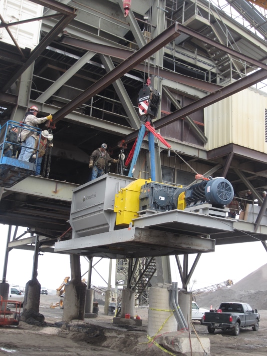
Stansteel Hotmix Parts & Service engineers provided a closer look at the elements that make up the pugmill.

Safety Notes

The first step with any plant maintenance is to make sure all inspections, markings or repairs happen while using proper OSHA Lockout/Tagout procedures. Ensure you have complete power disengagement before performing any inspections or repairs. For observations that require motors or other components to be operating, listen or watch for vibration and noises from a safe distance or rely on controls systems to provide feedback on specific parameters.

Some items will need immediate replacement, such as broken tips or excessive wear you notice when inspecting the pugmill shaft and mixer shanks.

For this series on assessing your asphalt plant for upcoming repairs and to avoid unplanned downtime, plant owners are reminded that only fully trained personnel should be allowed to conduct work on or around the equipment. For safety’s sake, the worker(s) should be fully trained on and act in accordance with all federal, state, county and local laws and regulations, and that includes OSHA and MSHA laws. You want your workers to be familiar with and act in accordance with the equipment specifications and manuals as well as your site-specific safety rules and regulations.

Pennsylvania Partners to Recycle More

Workers have to take responsibility for their own actions, inactions, consequences and results, but you can ensure the best possible outcome for their safety and your operation’s success when you take the time to train and educate each worker who has access to the equipment and material at your facility.

Always use OSHA Confined Space procedures.

After the pugmill is installed and working, don’t take production for granted. Keep your best production numbers going by performing routine, scheduled maintenance. All photos courtesy of Stansteel Hotmix Parts & Service, Louisville, Kentucky

Pugmill Parts

Starting with the exterior of the unit, make a note of any wear areas. Write down what you’ve noticed or type that into your inspection document and make a note to double-check when the repair is completed.

Lock Out/Tag Out For Safe Plant Maintenance

Next, remove the inspection doors to access the drive components. You’ll be looking specifically at the motors, reducers, sprockets and guards.

  • Check that motors have been operating at normal temperatures.
  • Has there been excessive noise or vibration during motor operation?
  • Are there any unusual odors from motors during operation?
  • Make sure all wiring connections are tight. (you don’t want loose wires)
  • Make sure all motors are properly ventilated.
  • Make sure all motors are connected to drive coupling.
  • Check and, if necessary, achieve proper oil levels in motors/reducers.
  • Make sure oil samples have been taken and make a note to have the results checked.
  • Inspect the pugmill shaft bearings.
  • Inspect the timing gears.

Moving away from the motors, let’s look at the heart of mixing.

  • Inspect the pugmill shaft and mixer shanks. Check for excessive wear and/or broken tips. Note this for immediate replacement.
  • Inspect the pugmill end liners. Check for excessive wear and note it for repair or immediate replacement.
  • Inspect the pugmill bottom liners. Check for excessive wear and note it for repair or immediate replacement.
  • Inspect the pugmill gate.
  • Inspect the air cylinder.
  • Inspect the air lines.
  • Inspect the solenoid valves.
  • Inspect the filter, regulator, lubricator (FRL) system.
  • Inspect the limit switches.
  • Inspect the gate slide rails.
  • Inspect the gate liners. Check for excessive wear and note it for repair or immediate replacement.
  • Inspect the liquid AC injection line. Check for leaks and note this for immediate repair.
  • Inspect all spray nozzles to make sure none are in danger of clogging.

Pugmill Systems Custom Mixing Solutions

If you have comments on any of the elements you’ve inspected, make those notes for your grounds crew or mechanic and set a date by which you’ll check back on the progress of repairs. A well-maintained and properly functioning pugmill is integral to the success of your batch plant or CCPR facility. Keeping it in good working order keeps your operation safe as well as efficient.

Using Combustion Quality Management in Burner Emissions Control

Focus on Performance: A Review of Burner Emissions Control Means for Asphalt Plants

Editor’s Note: The new Focus on Performance series from AsphaltPro Magazine allows OEMs and service providers in the industry to highlight asphalt professionals who have improved efficiencies and the bottom line through best practices and performance. This month’s installment from Malcolm Swanson, P.E., dives specifically into efficiencies gained through controlling the combustion process. As always, we’re honored to share Swanson’s knowledge with the industry.

The challenge of controlling emissions from fossil fuel burning industrial processes has been a major focus of industry since the passage of the Clean Air Acts of 1970 and 1990. So, the subject of this article is nothing new; but what makes the best emissions control methods work is not widely understood, even today. It’s good to know what works and why.

Use Low NOx Burners to Decrease Emissions

Chemicals Get A Bad Rap

Controlling burner emissions is really all about controlling formation and/or emission of certain chemicals. If you look at it from this point of view, our physical world is composed of chemicals. The cleanest things in nature, like pure water and fresh air, consist of chemical elements and various compounds of those elements. Air is mostly nitrogen—about 78%. Oxygen is the next most abundant element in air at about 21%. That leaves 1% for things like carbon dioxide, argon, hydrogen, helium, etc.

We can’t live without chemicals. In fact, we too are composed of chemicals. (I am not talking about our soul and spirit of course, just our bodies.)

There are chemicals that are harmful to the environment and to our health. However, even where “harmful” chemicals are concerned, the issue of danger is really about concentration.

For example, we all breathe carbon dioxide every minute of every day, but it doesn’t hurt us because normal air doesn’t contain a high enough concentration to damage our health. We can’t live without carbon dioxide because the plants that make oxygen and provide us with food need carbon dioxide to live and grow.

So, the real reason we try to control combustion process emissions is to keep the ambient concentrations of certain chemicals that have harmful potential at levels low enough to avoid harm. With that in mind, let’s consider what goes into controlling the oxides of nitrogen (NO and NO2, together referred to as NOX), carbon monoxide (CO), carbon dioxide (CO2), and total hydrocarbons (THCs).

What You Need to Know About Burner Size and Performance

Take Control of NOX

To narrow the focus of control efforts a bit, until climate change became the main issue, NOX had been considered the major offender, because it is a contributor to smog and can cause irritation of our respiratory systems. It has, therefore, received much attention. Controlling NOX emissions has been and remains difficult partly because some NOX control technologies tend to cause increased CO and CO2 emissions.

There are several different groups of technologies that have been developed to control NOX emissions. The major ones are combustion modification, exhaust gas treatment, staged combustion, fuel selection and combustion quality management. The last of these is probably not as familiar to many readers as the others. I will briefly discuss all five and then focus on the last.

To understand NOX emissions and how to control them, we must understand how they are created in the combustion process. NOX is formed through two different mechanisms and is referenced by those mechanisms—thermal and fuel.

  • Thermal NOX is formed in burner flames at very high temperature by burning the nitrogen in the air. This happens when fuel is burned, with air as the source of oxygen, at temperatures of about 2200°F and higher. With thermal NOX, the higher the temperature and the longer the time at high temperature, the more NOX is produced.
  • Fuel NOX is made when the “bound nitrogen” in the fuel compounds unites with oxygen in the flame. The amount of fuel NOX made is not so much related to time and temperature as it is to the amount of nitrogen in the fuel. Some fuels contain much more bound nitrogen than others. Basically, the heavier the fuel, the more bound nitrogen it contains. Coal, heavy oil, number 2 oil, propane and natural gas contain bound nitrogen, in this order from most to least. There isn’t much way to control how much fuel NOX is made in the burner flame except to use fuels that are low in bound nitrogen, like natural gas and propane, and burn as little fuel as possible by maximizing combustion and process efficiencies.

Because thermal NOX formation is strongly affected by temperature, much of the control efforts have been toward reducing flame temperature. Here are some ways that have been implemented. Flue Gas Recirculation (FGR), which is one of the means of reducing flame temperature, was the first effective means of NOX control implemented in asphalt plants.

FGR, which is also referred to as exhaust gas recirculation (EGR), is effective at reducing NOX, because it does two things that are unfavorable to NOX formation. First, it reduces temperature. It also reduces oxygen concentration in the flame making oxygen a little less available for bonding with nitrogen. However, FGR can only be pushed so far, because a deficiency of oxygen and low flame temperatures cause increased CO, CO2 production and exhaust gas volume.

Water injection directly into the flame was another early means of NOX control by suppression of flame temperature. Results were similar to FGR, but it was not quite as effective.

Staged combustion is another method of NOX control by reducing flame temperature and by creating zones where the fuel air mixture is not favorable for NOX production. The “stages” are points or areas within the combustion zone where portions of the total fuel and/or air are injected. Usually, a fuel rich zone is followed by a fuel lean zone so that the overall fuel air mixture is right but the mixture at each stage, rich or lean, is different from the final overall mixture. These methods are combustion modification techniques.

Treatments of the exhaust gases downstream of the process have also been used to reduce NOX, CO and TOCs but not so much in asphalt plants. In fact, my first patent in the asphalt industry was for catalytic reduction of NOX in the exhaust stream. The patent was issued but the equipment was never built due to there being less expensive alternatives.  Urea injection into the exhaust gas stream is another effective means of NOX reduction but it has seen little, if any, use in our industry.

Fuel selection has become the most common means of combustion emissions reduction, even though, by itself, it often does not provide enough emission reduction to comply with applicable regulations. Natural gas is currently the fuel of choice. It is usually available and affordable and contains the least amount of carbon and bound nitrogen of any fossil fuel. If natural gas is unavailable, propane is the next best thing.

Sustainability Tips for Asphalt Plant Dryer Burners

Combustion Quality Management

The discussion on Combustion Quality Management (my term) is the most interesting, in my opinion.

Burners, not just in this industry, but burners in general and especially large ones such as those we need for drying, have not been very good burners. For the most part, they have been perfectly adequate to provide the necessary heat and decent fuel efficiency for the drying process but have not been adequate to meet increasingly stringent emissions limits.

Most of the burners that have been used in this industry did not maintain consistent fuel air ratio throughout the normal firing range, but they were close enough for drying. It should be obvious that consistently maintaining the right fuel air ratio is critically important to controlling emissions. If you use too little air, the fuel burn will be incomplete and a lot of CO will be produced. Flame temperature will also rise causing excessive NOX production. If you go the other way with too much air the NOX may practically disappear because the flame is cooled by the excessive air but, again, CO emissions will increase because the “chilling” of the flame slows the chemical reaction of combustion and prevents complete burning. Too much air will also impact production rate by increasing exhaust gas volume.

However, let’s assume we have that part whipped. We can maintain the right ratio. There are some total air burners in the industry of which that assumption is nearly true. Our (this industry) burners still have not done a good job of emissions control for one reason: They do not mix the fuel and air very well.

When the fuel and air are not well mixed, what do you get for a flame? What you don’t get is a homogeneous mixture and, therefore, you don’t get a homogeneous flame. Rather you get a heterogeneous mixture and flame.

Think of the flame volume, with poor mixing, this way. It is as if the flame is composed of “pockets” of fuel-air mixture. Some pockets are fuel-rich while other pockets are fuel-lean. The rich pockets tend to burn hotter than the overall average flame temperature while the lean pockets burn cooler. We have both ratio problems—too rich and too lean—in one flame that is of the correct overall fuel air ratio. So, the flame makes too much NOX and too much CO even though the fuel air ratio is right.

These pockets of fuel air mixture of different ratios burn at different rates. This tends to make the flame large. For the typical 100 million BTU/hr gas burner the flame will be 12 to 14 feet long and 6 or 7 feet in diameter. That not only takes up a lot of the space in the dryer drum, but it extends time in the flame for every molecule. More time at temperature means more NOX.

This is what we have had. Now what do we do?

Dig deeper…down to the molecular level. Oxygen molecules prefer fuel molecules and do not like nitrogen molecules. Nevertheless, they will “marry” something if what they prefer is not readily available. Similarly, a carbon molecule will settle for one oxygen molecule if it can’t get two. So, the key to good clean burner emissions is mixing.

Mixing must be so good that nearly every fuel molecule ends up right next to an oxygen molecule. When that happens, the oxygen molecule will take the fuel and reject the nitrogen.

Of course, there isn’t enough fuel to suck up all the oxygen, so some NOX will be formed but it will be greatly reduced. Also, CO production will be minimal. Finally, combustion efficiency will be high, which reduces the fuel burn and, therefore, CO2 formation.

If it sounds crazy to say molecules have preferences, it won’t once you understand how it works. It’s called activation energy. To get the combustion reaction going, you must put some heat energy in and then you get much more back out. A match provides the activation energy to start the wax in a candle wick burning. The fuel/oxygen reaction requires less activation energy than the nitrogen/oxygen reaction. So, given equal availability of nitrogen and fuel to an oxygen molecule, the fuel/oxygen reaction is the one that will happen.

Something else that is really cool is that you get a flame with uniform temperature. There will be no hot or cold pockets. So, there are no “super emission producing” pockets in the flame. Also, because the fuel doesn’t have to waste time searching around to find an oxygen molecule to marry, marriage happens quickly, resulting in a very short flame.

The 100 million BTU/hr flame described above shrinks dramatically. It can be as small as 2 or 3 feet long and 2 or 3 feet in diameter. Flame volume shrinks to about 3% or 4% of that of the typical burner. That means very little time at flame temperature as well as no hot or cold pockets. Time in the flame drops to a few milliseconds.

Enhance EPDs with Burner Tech

Extraordinary Mixing

The question becomes, “How do you get that kind of extraordinary fuel air mixing?” You may be thinking “premix,” and you could be right, but most premix burners don’t get there. Premix is not necessarily better than nozzle mix. That is why there is such a thing as “lean-burn premix” firing. If the mixture is really good, the extra excess air of lean-burn premix isn’t needed. (The extra excess air is not a good thing because it reduces the plant production capacity by adding load to the exhaust system.)

The thoroughness of the mixture isn’t achieved just because it is premix or nozzle mix. It doesn’t really matter whether you get there by premixing the fuel and air upstream of the burner nozzle or do it at the nozzle. However, no one has been able yet to get that level of mixing in a nozzle-mix burner, as far as I know. I’m not saying that nozzle-mix burners are not good burners. There are some excellent nozzle-mix burners, but they aren’t ultra-low NOX burners.

Reliable Asphalt Products’ Vulcan Burner

Achieve the Best

As I share all these things, just so you know, I am not revealing any secrets. The basic science is the basic science. No one owns it. How to employ it to achieve these advantages has already been revealed in the patents. I am explaining in “English” what the patents and the science say in more complicated language.

The formation of carbon dioxide comes from burning fuels containing carbon. All fossil fuels contain carbon and hydrogen; hence, they are called hydrocarbon fuels. Those that contain the most carbon will produce the most carbon dioxide when burned. The ranking from most to least is the same as the ranking above for fuels containing the most bound nitrogen. With any particular fuel, the amount of carbon dioxide released is determined by efficiency. Obviously, burning more fuel makes more CO2 while burning less makes less. If you are going to burn a fossil fuel, the only means of CO2 control at the burner are fuel selection and efficiency.

Fuel selection is obvious: Use natural gas if possible.

Efficiency has two parts. First, there is combustion efficiency. The best possible combustion efficiency is basically burning all the fuel with the least possible amount of air. The least possible air is called “theoretical air” or “stoichiometric air.” In reality, burners never completely burn all the fuel and always use more air than the theoretical air. Combustion air, in excess of theoretical, is called “Excess Air.” Even the best commercial / industrial burners must have some excess air (usually about 25%) to get a good fuel burn. It might surprise some of us to know that minimizing burner emissions is not just about the burner.

The second part of efficiency is process efficiency. It is possible to have near perfect combustion and still have high fuel consumption and emissions because of waste in the downstream process. If you burn, for instance, 20% more fuel than is necessary, you make 20% more emissions. The telltale of poor process efficiency is high exhaust temperature and high equipment surface temperatures.

Good equipment insulation and good process heat transfer are the means of control for post combustion process efficiency. Asphalt plant dryer heat transfer efficiency is determined by controlling the exhaust gas temperature using the dryer flight system and drum rotational speed. Exhaust gas temperature should be maintained just above dewpoint temperature, with some allowance for cool and windy weather conditions. Dewpoint temperature in the plant exhaust stream actually changes very little. It is almost always in the range of 160 to 175°F. On a warm sunny day, it is safe to operate with 185°F stack temperature with no worry about mud in the baghouse. On a cold windy day, with uninsulated ductwork and baghouse, going up to 240°F stack temperature would be safer. With a good insulation system, cold and windy doesn’t matter. Operating with stack temperature near dewpoint provides much better process efficiency than is typically found among asphalt plants.

So, what is out there and available to manage your combustion quality? Astec has a low excess air premix burner that does the extraordinarily good mixing that I have described and achieves ultra-low NOX levels. There is also a good Hauck premix burner. Genco has a good, staged combustion burner. I am not trying to promote any particular burner. I just want to help increase understanding of the challenges and solutions of asphalt plant burner emissions control.

I hope, as you read everything above, that you didn’t brush over the importance of process efficiency as opposed to combustion efficiency. High fuel consumption caused by high stack temperature will increase emissions and decrease profits, even with the best burner in the world.

Malcolm Swanson, P.E., is the proprietor of e5 Engineers. For more information, he welcomes you to contact him at malcolme5engineers@gmail.com or (423) 667-6781.

INDOT Uses CCPR with AMICYCLE Emulsion Additive to Restore SR236

Embracing greener roadway strategy: cold recycling mix design at work 

Across the United States, road management agencies are moving beyond conventional repaving methods, embracing cold pavement recycling treatments to reduce environmental impact and stretch their budgets further on critical infrastructure.

Since 2018, the Indiana Department of Transportation (INDOT) has specified Cold Central Plant Recycling (CCPR) treatments on six state route rehabilitation contracts. Their treatment selection has been crucial to project success, through thoughtful consideration of options paired with an understanding of the in-situ pavement structure and the long-term needs of the network. In adopting CCPR as a rehabilitation technique, INDOT has gained a cost-effective, reliable and sustainable solution.

This diagram shows the profile of the State Route 236 project.

CCPR begins by milling reclaimed asphalt pavement (RAP) from a roadway and storing it at a nearby stockpile site. Often, with the majority of asphalt pavement removed, more invasive work can be done below the pavement whether utility excavation, subgrade treatment, or testing and inspection of underlying materials. Upon completion, a mobile mixing unit (pugmill) at the stockpile site blends the sized RAP with an asphalt emulsion, creating the CCPR mixture. The resulting mixture is then returned to the roadway as an intermediate pavement lift, reducing the demand for new materials.

The crew milled the existing asphalt 8 inches deep.

The crew milled the existing asphalt 8 inches deep.

A Closer Look at the State Route 236 CCPR Project

One of INDOT’s earliest and largest CCPR projects took place on State Route 236. During the 2021 and 2022 construction seasons, contractors collaborated to transform 13.36 miles of a narrow road with yielding subgrade into a wider, stabilized pavement structure topped with a hot-mix asphalt (HMA) surface course.

South Carolina’s First FDR Makes Royal Rehab

To minimize disruption, the project was executed in phases to accommodate local traffic. Each segment followed a multi-step rehabilitation process lasting approximately two months:

  1. Sampling and Mix Design: Pavement engineers took samples of the roadway material. In a lab, they designed and tested the correct composition of materials to create the new paving mixtures.
  2. Milling Existing Asphalt: The asphalt was milled to a depth of 8 inches, and the RAP was transported to a central processing yard no more than 10 miles from the site, minimizing haul times and emissions.
  3. Full Depth Reclamation (FDR): A nominal 3 inches of corrective aggregate was added to the exposed road base, then pulverized to a depth of 10 inches and stabilized with Portland cement.
  4. Creating the CCPR Mixture: The RAP was crushed, screened and sized to the required specifications before being mixed with a specially formulated engineered asphalt emulsion in a specially designed mobile mixing plant.
  5. Paving and Layering: Trucks delivered the CCPR mixture back to the job site, where it was laid in two 3-inch lifts using standard paving equipment. A 2-inch HMA lift was applied as the surface course, followed by permanent pavement markings.

This process not only optimized material reuse but also demonstrated the adaptability of CCPR in combination with other treatment types to tackle a variety of roadway conditions in a manner reflective of reconstruction.

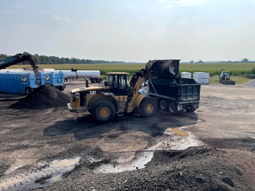
At the cold central plant recycling yard, the mix is blended in the pugmill and loaded into trucks for delivery to the job site.

At the cold central plant recycling yard, the mix is blended in the pugmill and loaded into trucks for delivery to the job site.

Deep Dive into CCPR Mix Design and Adaptability

Asphalt Materials Inc. (AMI) developed this specially formulated emulsion, branded as AMICYCLE. The CCPR mixture was sampled in the field and then laboratory-designed by Heritage Research Group (HRG). Their mix design was specific to the materials present and the construction details specified in the project plans. Quality Control (QC) for the CCPR was also overseen by HRG, ensuring the mixture met the standards outlined by the specification.

Best Practices of Full Depth Reclamation

Mix Design Process

In the lab, the RAP was crushed down and mixed with the engineered emulsion, which can be adjusted based on the expected temperatures and haul times, to produce 4-inch-diameter (100 mm) specimens for testing. The team created these specimens from both a medium and fine gradation, each mixed with three different levels of emulsion content. These six combinations underwent compression by a hydraulic press to test for stability and rutting resistance. Testing ensured the mix met durability standards before full-scale production.

With the optimal mixture selected, the HRG team worked closely with the pugmill operator to ensure the CCPR mix was precise, following the specifications outlined by INDOT for mix design and testing. HRG performed QC checks on the RAP gradation and mixture ratios throughout the process to ensure accuracy.

Here’s Why Cold Practices Are Hot Right Now

The mobile mixing plant (pugmill) used for the CCPR was custom-built by Pugmill Systems in Columbia, Tennessee. “AMI commissioned this unit to fit a specific combination of criteria not met by other machines on the market: tons per hour, ease of transportation and variable temperature handling,” said AMI’s Bruce Wehr. “[This] pugmill was designed to process a higher volume, up to 300 tons, of material per hour. Even with increased machine capacity and size, the unit was built with less weight so it could be hauled without permits, unlike many other pugmills. Finally, this machine had a wide operation range for liquid temperatures, handling materials ranging from CCPR at 100 degrees to Cold Patch at about 300 degrees. The Allen Bradley operating controls and mass flow meter allowed for this diversity of temperatures. With these capabilities, AMI’s custom mobile mixing plant was optimized for CCPR production.”

Once the CCPR mixture was placed, nuclear density gauge testing was performed to optimize the mixture’s compaction to ensure consistency and long-term performance. HRG monitored the curing of the CCPR lift, which can range in duration from 2 to 10 days, depending on environmental factors. INDOT specification requires the CCPR mat to reach a moisture content below 3.0% prior to HMA paving. The roadway was opened to local traffic immediately following the finish rolling operations.

Besides this meticulous testing and QC, continuity was another key to success. The same team that sampled the roadway’s millings also designed the mix and performed quality control throughout the entire process.

Here the team paves the first of two 3-inch lifts of cold central plant recycling (CCPR) mix made with AMICYCLE, a specially formulated emulsion. All images courtesy of AMI

Here the team paves the first of two 3-inch lifts of cold central plant recycling (CCPR) mix made with AMICYCLE, a specially formulated emulsion. All images courtesy of AMI

Key Contributors

The success of this ambitious project was made possible through collaboration. After the prime contractor, Milestone, crushed and sized the RAP stockpile, AMI, HRG and Pavement Maintenance Systems (PMS) managed the creation of the CCPR mixture at the central processing yard. PMS’s John Seabrooks operated the mobile mixing plant, while Wehr and Tim Zahrn of AMI supported the process, with HRG engineer Zach Robinson, who designed and tested the product mix.

Financial Impact

CCPR offers an alternative to conventional construction methods. For State Route 236, CCPR worked in place of an additional stone base and intermediate HMA layers. By using 100% of existing materials and reducing transportation costs, CCPR was 30% more cost-effective for the state than its HMA counterpart. The combination of FDR and CCPR also allowed for treatments at greater depth but at a lower cost per square yard, resulting in cost-effective, long-term pavement performance.

“If designed appropriately and used in the correct application, CCPR has comparable durability to traditional treatments,” explains Zach Robinson, Senior Engineer of Pavement Research at HRG.

NCAT Offers Cold Recycle Mix Design

Sustainability and Long-Term Environmental Impact 

On top of cost-efficiency, CCPR reduces greenhouse gas emissions by up to 50% compared to conventional construction methods, positioning the technology at the intersection of smart economic decisions and greener solutions. In recent years, the federal government has begun incentivizing carbon-conscious materials and offering grants to support the reduction of greenhouse gases.

INDOT has secured several grants that underscore the state’s commitment to environmentally conscious practices. The Federal Highway Administration’s “Climate Challenge” grant will help benchmark the environmental impact of pavement materials. Meanwhile, the funding awarded to INDOT from the Low-Carbon Transportation Materials (LCTM) grants program will support the adoption of materials and products with lower embodied carbon. By expanding its cold recycling initiatives and actively capturing federal funding, INDOT is steadily advancing its sustainability goals.

Indiana is one of many states committed to adopting more sustainable practices, including improving energy efficiency and reducing reliance on traditional material resources. Cold recycling treatments like CCPR support the components of a strategic and sustainable infrastructure plan, helping states improve their pavements while reducing lifecycle emissions.

The team paved two 3-inch lifts with the CCPR mix prior to a 2-inch surface layer of hot-mix asphalt.

The team paved two 3-inch lifts with the CCPR mix prior to a 2-inch surface layer of hot-mix asphalt.

Future Projects

CCPR is gaining traction across the Midwest. Beyond INDOT’s six projects, PMS and AMI have completed more than 10 CCPR projects in Ohio, Michigan and Illinois. In addition to states in the Midwest gaining traction with these processes, the Virginia Department of Transportation (VDOT) continues to lead with their adoption of cold recycling into highway reconstruction projects like I-81 and I-64. Their work further demonstrates the successful use of cold recycling technology on higher-volume interstates.

The SR 236 project showcases how innovative techniques like CCPR can redefine modern road construction. By combining cost efficiency, sustainability and adaptability, CCPR not only strengthens infrastructure but also reduces environmental impact.

As more agencies recognize the long-term benefits of cold recycling, its adoption is likely to grow — paving the way for greener, more resilient roadways across the nation. With key players like INDOT, AMI and HRG leading the charge, the future of sustainable infrastructure is promising.