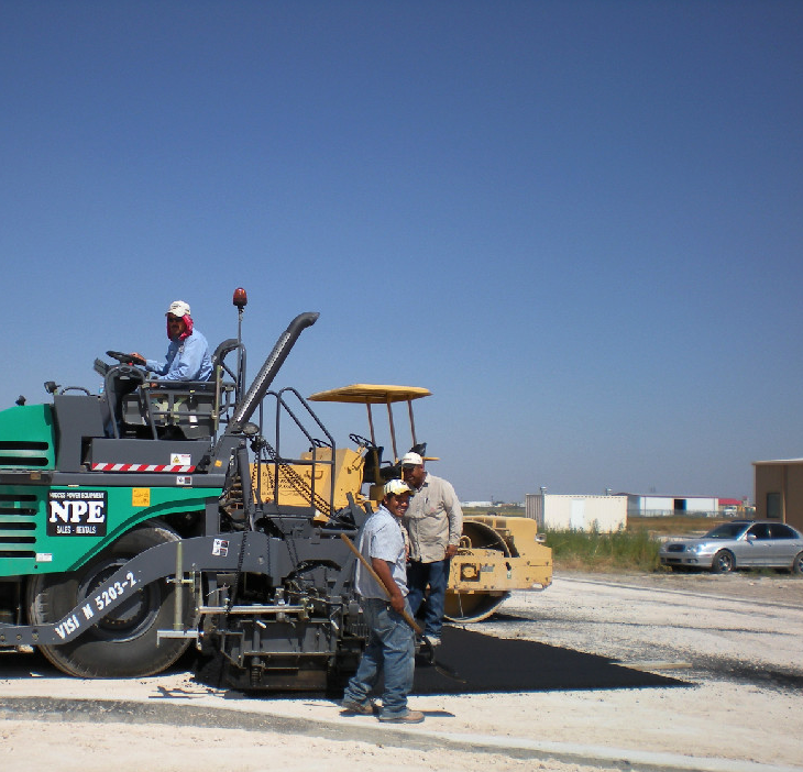
Prevent Temperature Segregation with a Thermal Profile

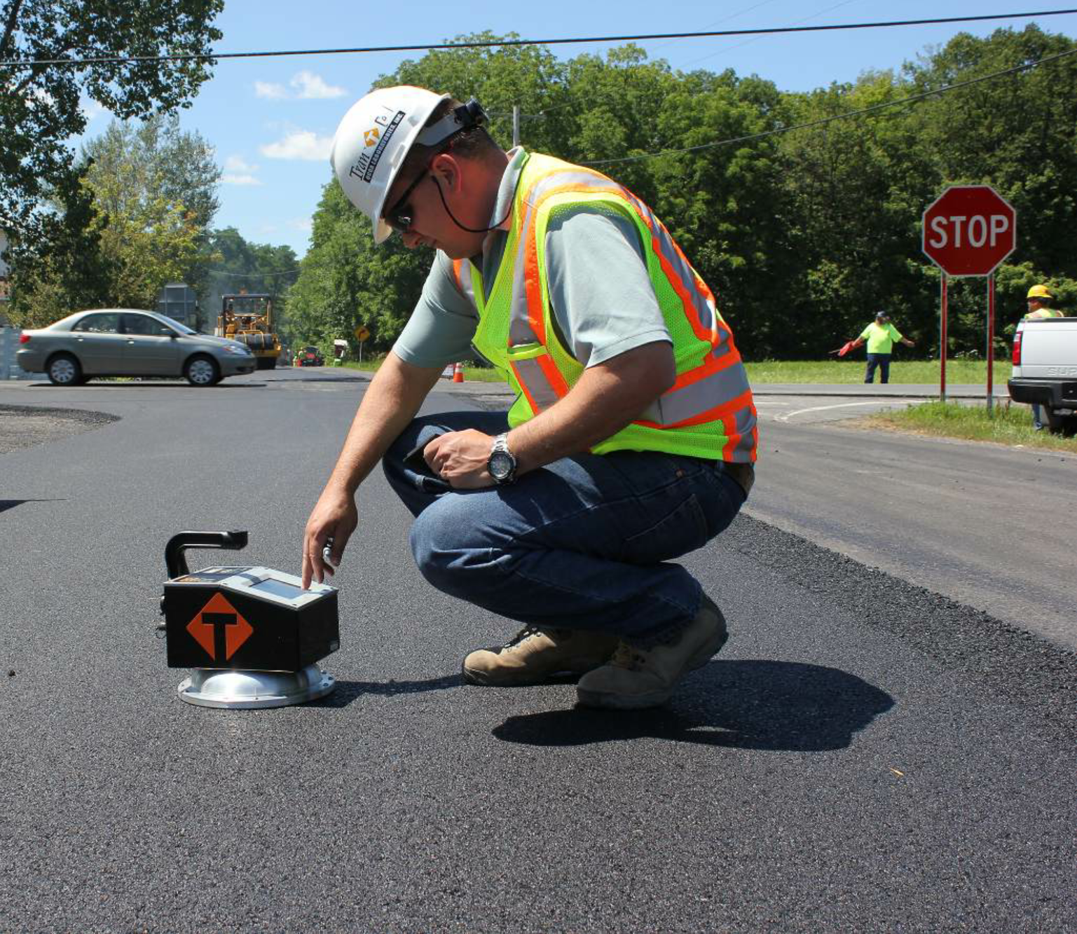
Paver-mounted thermal profiling scanning (PMTPS) is one facet of intelligent construction. Most readers of AsphaltPro Magazine are familiar with intelligent compaction, wherein data about the mat assists the roller operator in achieving optimum density.
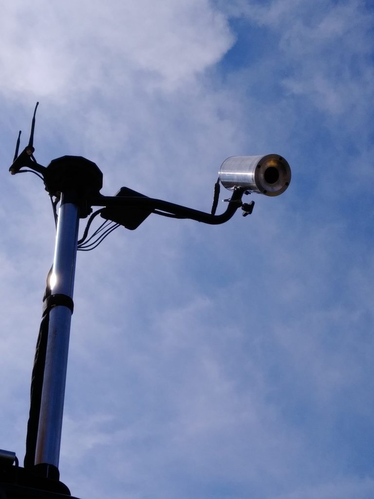
In PMTPS, a thermal “camera” is affixed to the back of the paver for the purpose of assisting the paving crew in monitoring, and thus lessening the chances for, temperature segregation in the mat. The researchers at Transtec Group Inc., Austin, Texas, shared at their intelligentconstruction.com site:

“Normally, every 50-meter section of full-width temperature profiles is analyzed to determine the levels of temperature segregation. Example methods are the US AASHTO PP80 standard…and an improved Thermal Segregation Index (TSI) method developed by the Minnesota Department of Transportation (MnDOT) and The Transtec Group’s Veta team.”

NB West Wins Quality Award for I-44

Daniel Oesch, P.E., field materials engineer for the Missouri Department of Transportation (MoDOT), explained: “MoDOT has awarded 69 projects to date with both IC and PMTPS technologies. The effort gained momentum in 2016 after receiving an Accelerated Innovation Deployment grant from the Federal Highway Administration providing additional resources for the first 13 projects. During the 2020 construction season, 29 projects will be underway utilizing these technologies. This year, we have deployed a fleet of agency owner GPS tracking units, which are being circulated on the IC rollers in order to perform quality assurance (QA) on the data being collected by the contractors’ equipment. In addition to spot temperature readings, this year thermal images will also be used for QA of the PMTPS systems.”

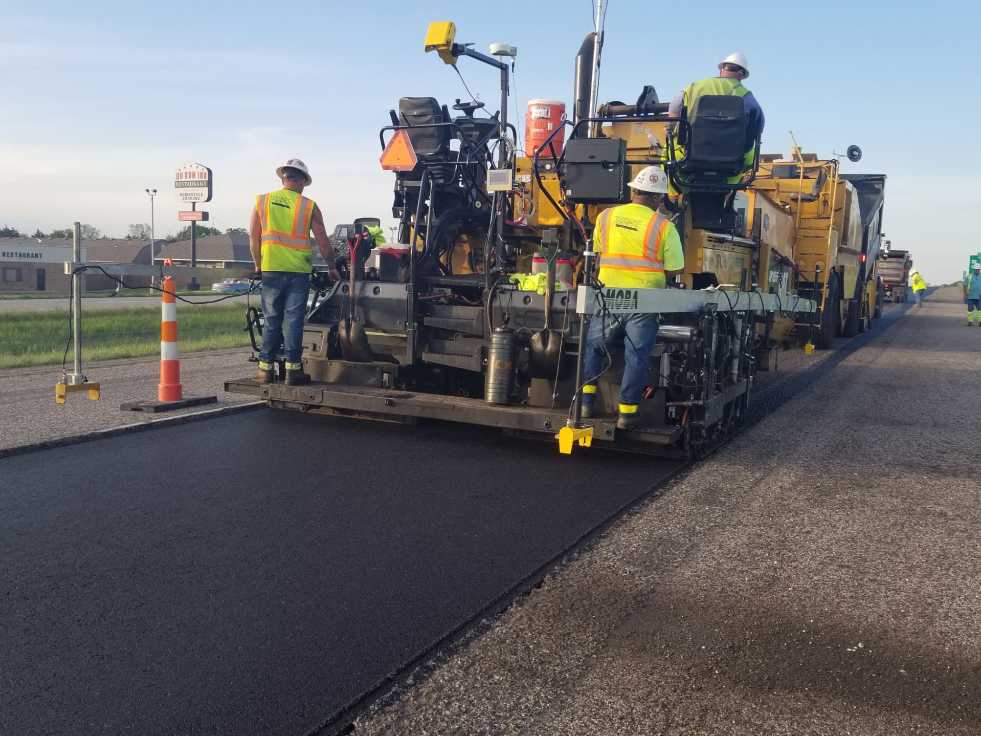
Henry Polk of BOMAG Americas, Ridgeway, South Carolina, explained that the MOBA thermal imaging system is the preferred vendor Bomag recommends for use with its paving equipment. He shared that the MOBA thermal camera captures and stores the readings from across the width of the mat, allowing the foreman to download and share the data via a USB stick. While the thermal cameras available today don’t penetrate the mat, the temperatures measured and recorded from the surface give contractors a data point not easily available before.

“It only shows the surface temperature, but it’s still relative to segregation,” Polk said. “Thermal segregation is far worse than material segregation. Being able to see it on the surface is better than not being able to see it at all.”

The team at Caterpillar Paving Products, Peoria, Illinois, has a similar explanation. They state on their website: “Thermal mapping monitors the surface temperatures of the asphalt utilizing an infrared camera and a Global Navigation Satellite System (GNSS) enabled by RTK accuracy. Viewing real time temperatures, contractors can identify variations and take action to manage the plant-to-paver delivery process and fine-tune paving practices for more uniform lay-down temperatures.”

Caterpillar Paving Products displayed its thermal mapping camera at its outdoor booth at CONEXPO-CON/AGG 2020.

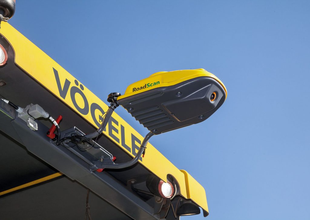
At the Wirtgen Innovation Days event in the fall of 2018, product managers discussed the merits of the Vogele RoadScan. This infrared temperature measurement system was also on display at CONEXPO-CON/AGG 2020 in Las Vegas. It’s designed to make quality measurable by verifying you’re paving at a constant temperature. It’s a non-contact temperature measurement system that scans the whole of the asphalt pavement behind the screed. A GPS receiver is also mounted in the housing for the infrared camera, to record the exact position of the temperature data. External parameters affecting paving are recorded as well. The maximum measuring width of 10 meters is made up of 40 squares measuring 25 by 25 centimeters. Each of these grid squares contains up to 16 individual measuring points, from which a mean value is calculated. The measurable temperature range is between 0 and 250 degrees C, with a tolerance of +/- 2 degrees C. RoadScan saves the measured data in the paver operator’s ErgoPlus 3 console. After paving, the data can be transferred to a memory stick.

The Vogele RoadScan infrared temperature measurement system captures a host of data to inform the crew of conditions present at the moment of readings.

As part of its Pavelink system, Topcon Positioning Systems offers the thermal mapper, which affixes to any paver to monitor the temperature of the entire width of the mat. It shows the operator, in real time, the average temperature of the previous lot as well as thermal segregation and for the overall jobsite. This means the foreman can see immediately if there’s a temperature problem creeping into the operation.


Preventing segregation is one step toward quality control for contractors. Equipment that can re-blend mix to keep cool spots from making their way through the train and to the mat is a helpful tool. “Our remix machine re-blends it and does away with the thermal segregation,” Polk said.

Topcon’s Pavelink Connects All Project Stakeholders

To ensure remixing machines ahead of the paver—or at the paver—have done their jobs, or to ensure all trucks have delivered consistent loads to the process, the thermal cameras offer an extra QC/QA measure. If the foreman and paver operator monitor the temperature readings gathered moment-by-moment, they can monitor temperatures in real time and make adjustments as needed.

This ensures the mix being delivered from the plant, to the head of material, and to the mat has a uniform temperature and a consistent, top quality.


This article originally appeared as a sidebar alongside this article about NB West’s award-winning mill-and-fill project on I-44, that required paver-mounted thermal profiling scanning (PMTPS).

Schellinger Construction Hits Notch Wedge Joint Density Specs

It isn’t much of a stretch to say that Schellinger Construction, Columbia Falls, Montana, never uses the same mix twice. Of course they do, but the general contractor’s paving crews are almost always on the move, transporting the company’s Astec 400 ton-per-hour double barrel and CMI E3 400 asphalt plant to jobs all around central and western Montana.

One constant, however, is the need to properly compact notch wedge joints.

“Around 80 to 90 percent of our jobs are for the Montana Department of Transportation,” said Schellinger’s Manager of Asphalt Operations Bob Warren.

That’s why Schellinger purchased a notched wedge joint and pneumatic roller system from Willow Designs, East Berlin, Pa.

“Montana continues to raise the bar on joint density,” Warren said. “This notch wedge joint and pneumatic roller system gives you a fighting chance to hit compaction on that edge.”

Specifications for gently sloping safety edges, also known as notch wedge joints, have become common across North America. Montana’s Department of Transportation requires notch wedge joints on its projects, and began offering a pay factor related to joint compaction over the last few years, Warren said.

“It’s both a method spec and an end-result penalty,” Warren added. “There is money to be made, or lost, with joint compaction. We take it very seriously.”

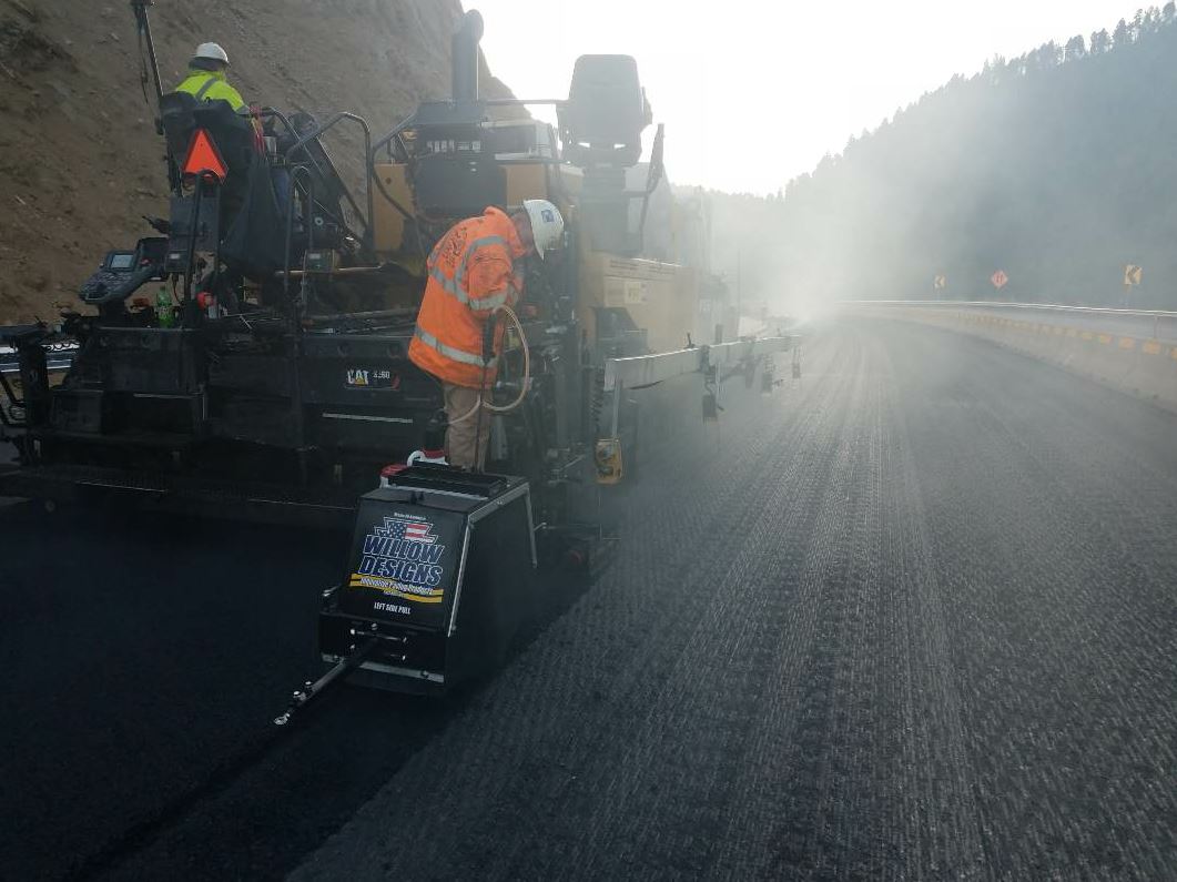
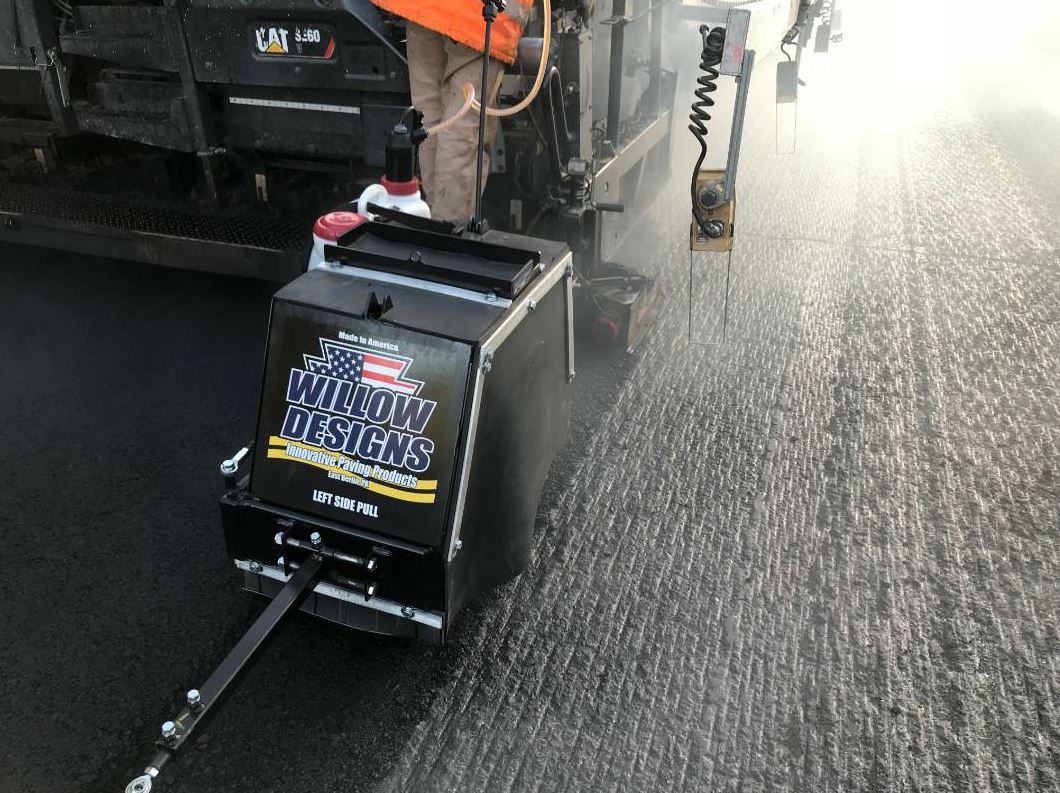
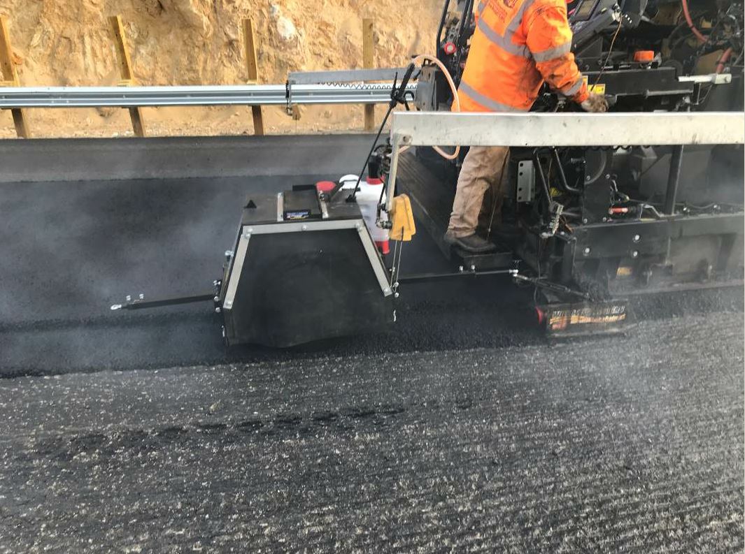
Schellinger Construction purchased the notch wedge joint apparatus from Willow Designs in 2017. In 2018, the company added Willow’s pneumatic roller, seen here, behind it.

Schellinger Construction purchased the notch wedge joint apparatus from Willow Designs in 2017. In 2018, the company added Willow’s pneumatic roller, seen here, behind it.

Prior to purchasing the notch wedge joint system from Willow, Warren had built his own device around four years ago. “It worked fairly well, but this one is way more user friendly and adjustable,” Warren said, adding that Willow’s notch wedge joint device can be raised or lowered, angles can be adjusted, and there is a specific device for both the right and left side of the paver (the pneumatic roller is adjustable to either side). “My homemade one wasn’t nearly as handy or as portable as this one.”

The results of his homemade device were also a bit more hit or miss, Warren added.

Warren began looking for a more reliable solution. “I asked around and found that a lot of my competitors were using Willow’s device,” he said.

Last year, the company purchased the notch wedge joint apparatus. This year, they tacked the pneumatic roller, which they call R2D2 for the way it wobbles along behind the paver, behind the notch wedge joint apparatus to ensure proper compaction of the joint.

So far, Schellinger’s crew has used the notch wedge joint device on about a dozen jobs, and its new pneumatic roller on two.

In September and October of 2018, the crew used the entire system on an 8-mile job on Interstate 15 near Boulder, between Helena and Butte, Montana. Schellinger Construction was selected as the low bidder on the $8.5 million project, which included milling and replacing 2.4 inches of asphalt across 16 lane miles. The job required a total of 36,000 tons of hot-mix asphalt.

The crew had to contend with many curves and 10 bridges where the interstate passes over the Boulder River. “That’s more than 60 bridge connections,” Warren said.

Warren estimates that 80 to 90 percent of Schellinger Construction’s jobs are for the Montana Department of Transportation.

Warren estimates that 80 to 90 percent of Schellinger Construction’s jobs are for the Montana Department of Transportation.

Other challenges included having one lift with which to achieve a smooth ride, on top of a 2.4-inch milled (rather than profile milled) surface, no less. There were also the challenges of varying conditions along the road, such as intermittent sunshine, and the properties of PG 70-28 ¾-inch asphalt.

“PG 70-28 can be pretty stiff,” Warren said. “Compaction can be hard to achieve with that AC and those conditions.”

Schellinger earned bonuses for rideability, volumetrics and density on the Boulder job. They even made a small bonus on joint density. Warren estimates that the crew hit the joint density spec 80 to 85 percent of the time, compared to 70 to 75 percent of the time before they began using the pneumatic roller.


“It definitely improved our compaction on the Boulder project and left behind a better looking mat on the surface of the wedge,” Warren said. The other job it used the entire system on was a $12 million job west of Missoula, using PG 64-28 half-inch mix. On that job, Warren said, the joint density was a bit more hit-or-miss.

“The spec is 91 to 94 percent within 6 inches of the centerline joint, and while we had a lot in that range, we also had a smattering of 88s, 89s and 90s,” Warren said. “I really wanted to get to the point where our minimum was 91.”

On the first job with the pneumatic roller, Willow Designs’ proprietor, Jerod Willow, came to Schellinger’s job site to provide guidance on the system.

“It’s easy to get stuck doing the same things the same way just because that’s how we’ve always done it,” Warren said. “It was good to have a fresh set of eyes watch our operation and offer new ideas, especially when it’s someone with Jerod’s background and his focus on this one aspect of paving.”

Specifications for gently sloping safety edges, also known as notch wedge joints, have become common across North America. Montana’s Department of Transportation requires notch wedge joints on its projects

Specifications for gently sloping safety edges, also known as notch wedge joints, have become common across North America. Montana’s Department of Transportation requires notch wedge joints on its projects.

Results were already improving by their second job with the system.

“We still had a couple high or low results, but a lot of that was getting used to a different apparatus,” Warren said. “I think the more projects we put under our belt using it, the more we will improve.”

Willow offered a number of tips, many of which are available in the sidebar of this article.

Clients who purchase a notch wedge pneumatic roller get one shift of support anywhere in the united States or Canada from Jerod Willow, who has more than 23 years of experience in asphalt laydown and 16 years of knowledge using notch wedge joints.

For example, Willow recommends using a double application of tack to really keep the joint together, assist in filling the voids of any minor segregation in the wedge, and aid in joint density. He also recommends staying 12 to 15 inches to the inside of the joint on the first roller pass to help stabilize the material over the notch wedge joint, and then compact the section skipped on the first pass during the second pass.

“The number one thing is the addition of the pneumatic roller,” Warren said. “The second thing is changing the breakdown sequence to force more mix into the joint.”

“We’d probably be consistently hitting 100 percent [on our joint density] if our operation wasn’t portable by nature,” Warren said. “We don’t use the same plants, the same mix, the same materials on every job, so there is always a learning curve.”

Although the unique challenges that come with Schellinger’s portable asphalt operations will always be there–with or without a notch wedge joint system–Warren is keen to improve consistencies wherever he can and the crew is rapidly closing in on any learning curve surrounding how to use Willow’s notch wedge joint and pneumatic roller system.

“We have a small sample size to look at, but the philosophy of it and the thought behind it is correct,” Warren said. “There’s no doubt that the notch wedge and pneumatic roller is the way to do it.”


Best Practices of Building, Compacting Notch Wedge Joints

Jared Willow, proprietor of Willow Designs, shares his top tips for making notch wedge joints with Willow Designs’ system.

Depth

Willow recommends that the depth of the notch be between 35 and 50 percent of the compacted mat, with 40 percent being ideal. When dialing in the depth of the notch, he warns to compensate for the compaction depth of the mat, and to check the notch’s depth after the first roller finishes its compaction pattern.

Wedge

The wedge, Willow adds, should be as smooth as the mat behind the paver screed. “The edge–the thinnest part of the wedge–should be no less than the maximum nominal aggregate size in the HMA being placed,” he said. “This will help to eliminate depth segregation.”

“A common misconception is running the notch wedge joint as tight as possible, to the point that the wedge is almost non-existent, with major depth segregation in the mix in the 12-inch wedge,” Willow said. “The major problem with this is the 12-inch segregated wedge in the joint will never get compacted and will be destined for failure.”

Tack

Willow recommends a double application of tack, “if using anything other than PG tack codes” like Pennsylvania’s specs. He suggests spraying the vertical edge of the notch wedge and the entire 12-inch wedge.

“We like to see the tack so heavy in the joint that it’s almost running off the wedge,” Willow said, “because we don’t want the joint to come apart and if there is any minor segregation in the wedge this will help fill the voids and aid in joint density.”

Compaction

To properly compact your notch wedge, placed at an appropriate depth, Willow recommends using the notch wedge pneumatic roller.

The pneumatic roller has a patent-pending steering system, which allows for lateral adjustment of the pneumatic roller tracks behind the paver. It assists with the stabilization of the 12-inch wedge.

“We don’t like to call it compaction because we do not want to fully densify the 12-inch wedge until the adjacent lane is placed on top of it,” Willow said, adding that this is why Willow Designs uses a pneumatic rather than a steel drum. “Since the wedge is essentially a thin lift, using a pneumatic will knead and tighten the mix in the 12-inch wedge without breaking aggregate.”

The sidewall of the pneumatic tire roller will also re-establish the vertical edge of the notch. “As the notch wedge joint is being built at the paver, segregation takes place where the edge of the mat and the notch wedge joint meet,” Willow said. “We like to refer to this as ‘the fluff in the joint’.”

The “fluff in the joint” can be eliminated by adjusting the steering system on the pneumatic roller to cut the mainline mat by 1/2 an inch to 1 1/2 inches to create a new vertical edge for the notch. Willow said this will yield higher density numbers on the open edge of the joint prior to placing the second pass or adjacent lane.

When doing the rest of your rolling, Willow recommends staying 12 to 15 inches to the inside of the joint on the first roller pass. “This stabilizes the material over top of the notch wedge joint,” he said. On the second roller pass, the roller should shift over to compact the 12 to 15-inch section it skipped on the first pass. “This will force the material straight down into the joint.”

Then, he said, continue rolling the rest of the mat as normal.

Match the Joint

Whether paving the second pass or an adjacent lane, Willow said it’s critical to overlap while matching the joint. “You don’t want an open joint, but you also don’t want too much overlap,” he added. The overlap should be between 1/2 an inch to 2 inches, based on the HMA mix and depth.

“Match height on the joint is also critical,” Willow said. “This is where you will have to experiment a little based on different mixes, depth of the notch, and depth of the HMA mix total.”

A trick he uses when matching the joint on a notch wedge joint is to check the mat depth 15 inches from the joint. “If this area is short on HMA mix depth, increase the main screed depth while adding a little positive slope on the joint matching extension so the joint will still roll in during compaction,” Willow said. “This minor adjustment will still provide a flat profile of the finish pavement on the second adjacent pass after compaction, but will provide more material in the joint to get density.

“From a visual standpoint on a properly matched joint, we like to see a white line of crushed aggregate the width of the overlap on the joint,” Willow said. “A joint that disappears is a future failure.”

Equipment Maintenance

It’s imperative to use a green release agent prior to paving, one that is not cut with water.

“It’s intended for the pneumatic tire to heat up from the HMA mix,” Willow said. “The green release agent will allow this to occur while still providing lubrication so the HMA doesn’t stick to the tire. Release agents cut with water do the exact opposite. They cool the tire, which will cause major pick up of HMA mix on the tire.”

Once the pneumatic tire is heated up, reapplication of release agent should be every 15 to 45 minutes, depending on the mix being placed.

Paving Speed Changes Quality

One of the many stressful sights for a paver operator is a line of haul trucks parked ahead of the paving train. Each truck holds at least 18 tons of cooling hot-mix asphalt (HMA) and it’s his job to get that material under the screed. Now. Time is money. Adrenaline tells him to speed up.

Good training tells him to keep a steady pace.

To set an adequate paving speed, the foreman on the job and the paver operator need to have confidence in a host of factors, including:

  • the production at the plant;
  • the communication skills of the plant operator;
  • the trucking foreman;
  • the haul truck drivers following directions;
  • the weather forecast;
  • the paving and compaction train equipment and its uptime; and
  • the equipment operators’ training/skill levels.

For the first part of this article, let’s pretend you have the ideal paving scenario. We’ll assume each person on the job knows what he’s responsible for and when.

The plant has an excellent uptime and maintenance track record, and the plant operator is staying in touch with the foreman to let him know everything is running smoothly. The trucks are arriving in a perfect round-robin interval (see sidebar on below, “Use the MTV Properly”). The dump man is communicating clearly with each truck driver. The compaction train has planned a stellar rolling pattern and has finely-tuned equipment for getting compaction at the speed you select.

With all these factors going smoothly, the paver operator can watch the flow of material from the hopper to the screed. He will watch so that the level of mix at the auger (the head of material) will remain consistent across the width of the augers. To keep the height of material consistent, he will have to maintain a consistent speed. He will set the paver speed and auger rotation so the height of the mix reaches the center of the augers. He won’t radically speed up or suddenly slow down.

The screed operator will be able to help maintain a consistent head of material by watching for any changes from the feed sensors. These will be set for the height and speed of the job, and they need to be monitored for change. Typically, you’ll affix the feed sensor to the endgate; direct the sensor’s eye toward the mound at a 45 degree angle so it monitors the churning material correctly.

You don’t want to set the sensor directly above the mound and point it straight down. Keep track of how high material builds up when extending or retracting the endgate so you don’t accidentally cover the sensor. Once it gets sticky material on its eye, you’ve got to clean it to keep it working right. The beam it sends to measure distance to the pile won’t get through a film of gunk.

There’s an App for That

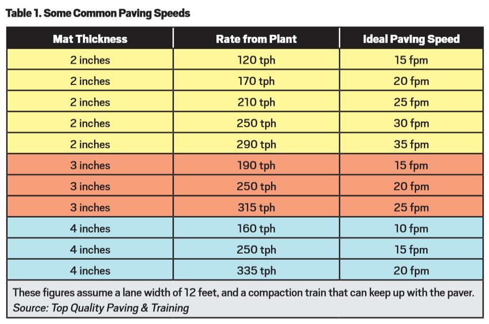
To set paving speed, the operator has all kinds of tools available to him. Paving experts have created charts and tables over the years to help you select a speed based on depth and width and factoring in some mix design elements. Use them.

The team at Roadtec, Chattanooga, Tennessee, has one here. You’ll also find download links for the calculator from Caterpillar here. Depending on the level of confidence you have in your truck delivery, you can plan to pave a couple feet per minute more slowly than the chart tells you to pave, or a couple feet per minute more quickly.

Depending on the wind/ambient conditions you anticipate for the day, you may wish to put in a call to the plant to ask for faster loadout, and then plan for faster paving speed.

With all these variables factored in, you can set a reasonable speed that you can reasonably expect to maintain. The point is, once the paver operator establishes the paving speed for the day, he will want to stick to it. Don’t speed up to get through a line of trucks so you can take a break.

The “spot” where you stop to relax will end up being an area that the state inspector finds fault with. If the plant operator has more trucks loaded and sent to your project than you anticipated, this is a problem for the foreman to work on with the trucking foreman. Changing paver speed changes the angle of attack, which changes the quality of compaction the screed offers.

During the Wirtgen Technology Days event held at the Center for Technology and Training in Antioch, Tennessee, March 29, Laikram “Nars” Narsingh, manager, commercial support and development – Vögele, shared with the audience that the forces acting on the free-floating screed are then acting on the mat. Let’s look at those forces real quickly.

  1. The tow arm offers pulling force.
  2. The weight of the screed offers a downward force.
  3. The material under the screed offers a reaction force.
  4. The material coming out the back of the screed offers a friction (or shear) force between the material and the screed.
  5. The head of material offers a pushing force against the screed.

When all of these forces are at equilibrium, or balanced, Nars explained, you get the constant mat depth. When one of the forces experiences a change, it causes the screed to either rise or fall.

By speeding up or slowing down, the paver operator disrupts the equilibrium of forces and changes the resistance of the screed against the head of material. This will result in a change in the mat thickness, a change in the performance of the screed’s compactive effort, and lower quality paving.

Of course, not all projects have perfect conditions all day long. If you must slow down because the foreman got a call from the plant and learned that there’s an interruption in delivery, adjust the paving speed slowly. Paving Consultant John Ball reminds operators they can’t suddenly drop from paving 35 feet per minute to 15 feet per minute without suffering the consequences.

Radical changes in speed cause the angle of attack to change, which creates a change in the mat. The pulling force changes too quickly. In the case of a sudden slow-down, you’ll have a short wave, or even a bump, in the mat. Waves cannot be rolled out. Let automation, feed sensors and best practices help you keep a consistent head of material feeding under the screed.


Time the Trucks

Let’s say it takes 3 to 4 minutes to load the haul truck with the preferred three-drop method. The tarp is automated to slide or lower into place while the driver gets the ticket, taking another 2 minutes. Time waiting to dump should be minimal, but let’s say that’s 10 to 15 minutes on the jobsite.

The truck is engaged with the hopper for 5 minutes. The driver pulls away and has 5 minutes for cleanup in the designated area. All you need to know is the actual travel time (with traffic delays) from the plant to the work zone, and return time, to estimate the time needed for each truck to complete a cycle.

How to Roll for Bonus, Part 2—Ideas for Perfect Compaction

If misalignment of the screed sections leaves a line in the mat, the roller operator is called on to smooth it out. Mat imperfections, divots, cool spots, anything that isn’t perfect gets left to the breakdown, intermediate and finish rollers to take care of. That means the roller operator’s equipment must be in perfect working order, as we discussed in September, and his skills must be honed with excellent training and continued review. For this part of our rolling series, we’re going to teach your roller operators how to do a bonus-worthy job.
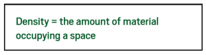
The instruction in this article will begin with the shift start-up, which requires input from the quality control (QC) tech on the project. Then we provide an in-depth look at rolling patterns and what influences them for best compaction. We’ll wrap up with a quick review of intelligent compaction (IC) use. This article will teach your roller operators the “what” and “why” behind getting density without crushing rock, and how to do it all efficiently, effectively and with minimal downtime.

Before we get into the shift start-up, let’s discuss one fundamental that a number of resources agreed upon:

As the operator of the compaction equipment, you have the critical job of safeguarding the pavement layers against deformation. Once the subgrade, capping and subbase layers for the road’s structure are in place, it will be your responsibility to compact the asphalt base layer, intermediate (binder) layer, and surface (wearing/finishing) layer to perfection. The purpose of compaction is to protect the whole system from deformation, water intrusion and more.

As the roller operator, you are a vital member of the paving team. You are the person who gets the aggregates and fines that are in the mix to fit together like a puzzle within their layers, so that they form a strong and supportive, yet still fl
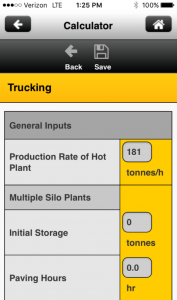
The Paving Amplitude Calculator App from Caterpillar Paving Products, Peoria, Illinois, is designed to help the operator determine the proper amplitude setting for the roller. The user inputs a number of metrics and the tool processes the information to offer a recommended amplitude setting and instruction on how to set up the vibratory system to provide the recommended output. Photo courtesy Caterpillar Paving Products, Peoria, Illinois.

The Paving Amplitude Calculator App from Caterpillar Paving Products, Peoria, Illinois, is designed to help the operator determine the proper amplitude setting for the roller. The user inputs a number of metrics and the tool processes the information to offer a recommended amplitude setting and instruction on how to set up the vibratory system to provide the recommended output. Photo courtesy Caterpillar Paving Products, Peoria, Illinois.

exible, pavement. Simply put, the roller operator squeezes out a percentage of air voids.

Each state department of transportation (DOT) has specs for the percent of density the compaction team should achieve, depending on the mix design and the layer you’re working on. That’s one of the many reasons the roller operators, and all members of the rolling team, need to know more than what type of equipment they’re working with. They need a meeting at the start of the day to learn the what, why and how for the rolling pattern(s).

Start the Day

In the old days of all-visual control, the supervisor was generally the one giving the roller operator his cues. Now that it’s a numbers game out there, the QC technician typically calls the shots, according to industry consultant John Ball of Top Quality Paving & Training, Manchester, New Hampshire. Your QC technician needs to hold a meeting with the roller operators to start the day off right. This huddle is usually a separate meeting for the QC team, and it’s a vital step to make sure each member of the rolling train knows what he can expect for the day and what is expected of him on the job overall. The team has specific goals for this conversation, which a number of experts weighed in on.

First, the QC officer—usually with support from the project supervisor—will handle the management of this meeting and its outcome. He will bring together the breakdown roller operator(s), intermediate roller operator, finish roller operator, and the general laborers who run the plate compactor and assist with fueling and filling water tanks.

Second, the QC tech will make sure each equipment operator knows the width of the drums on his equipment and the width of the lanes—or passes—being laid. Knowing drum width and lane width is vital for figuring the rolling pattern.

Third, the QC tech will make sure each equipment operator knows the type of mix the crew is working with that day, at what temperature they expect it to arrive from the plant, and at what depth it will be placed. Knowing the type, temperature and thickness of the mix is vital for setting amplitude and frequency, and impactment spacing and rolling speed. These elements are interconnected for success, so let’s give operators an overview of them here.

  • Amplitude is the height the drum “jumps” off the mat during vibration, as described by Ball. Depending on the thickness of the lift/layer and coarseness of the mix, the amplitude of the breakdown roller will be set to high, medium or low. For example, thick lifts (2 or 3 inches in North America) can take higher amplitude than thin lifts (0.5 or 1 inch). Original equipment operators (OEMs) have developed technology to help QC techs and operators figure settings based on actual conditions at the jobsite. For example, Caterpillar Paving Products has the Paving Amplitude Calculator App to help you determine the proper amplitude setting for the roller. First, you input the metrics that the app requests. Then the tool processes the information to offer a recommended amplitude setting. It also offers instruction on how to set up the vibratory system so the operator can achieve the recommended output.
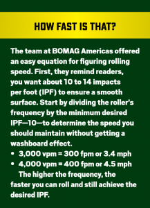
  • Frequency is the strength or force of the vibration. It is measured in vibrations per minute (vpm). Depending on the temperature and coarseness of the mix, the frequency of the breakdown roller is typically set between 2,500 and 4,000 vpm. The team from Sakai America shares on its website: “Frequency is simply the number of times per minute that the eccentric shaft rotates within the drum. 4000 vpm means the shaft rotates 4000 times per minute…”
  • Impactment space, which Ball considers the most important setting to monitor, is the number of times—per foot—that the drum “hits” the mat. It is measured in feet per minute (fpm). Impact spacing will not be less than 10 impacts per foot (IPF), which is traveling at about 380 fpm, or you could see waves or dips in the mat. You will not set the impact spacing higher than 14 IPF, or you could end up with ripples in the mat. Remember that impactment spacing dictates your speed.
  • Oscillation is the back-and-forth action of two, unbalanced shafts within the roller drum. The team at Hamm explains the concept: “The unbalances are offset by 180 degrees. This causes the drum to carry out a rapidly alternating forward-backward rotary movement, with the result that the compaction energy is directed into the [pavement] tangentially to the front and rear in the form of shear forces. In contrast to a vibrating drum, it acts dynamically on the [surface] all the time. Because the drum is always in contact with the ground, there is also a constant static load due to the weight of the machine.”
When the operators understand the amplitude, frequency, impactment spacing and other settings of the breakdown and other compactors, they will be better able to set the values for the current job’s mix design, temperature and thickness. As mentioned already, the thick mat will allow stronger—or higher—amplitude. These settings are more easily programmed today due to the microprocessors built into the machines. Ball says it’s no longer a guessing game.

Let’s dive into some basic rolling patterns and a few mix designs that influence change in those patterns.

Develop Your Best Rolling Pattern

Part 1. Widths

During the compaction team meeting, the QC tech and roller operator will help determine the rolling pattern. This should be based on width of the mat and width of the rollers, as well as the mix design parameters (including its delivery temperature), paving speed, and ambient and ground temperatures. We’ll look at temperatures and mix design influences again in just a moment; let’s do some width calculations right here.

When selecting the equipment for the job, the project manager will have considered which asphalt compactors in the company’s fleet would be perfect for the lanes to be paved. If you’re paving a 12-foot-wide lane, your manager probably didn’t pick a 54-inch roller for the job. Ball explained that it’s too narrow to achieve compaction before the mat cools.

To get the most efficient number of roller passes applied to the mat, you want a drum of sufficient width. The 12-foot lane is 144 inches wide. The wise project manager wants to put a roller with a 78-inch drum (or even an 84-inch drum) in the breakdown position. The 84-inch drum is a bit wider than necessary, but its heavier weight can assist in compaction.

Consider the roller with a 54-inch drum width for a moment. If you roll up toward the screed and back for one pass, you’ve covered 54 inches of the 144-inch mat; let’s say that takes three minutes. Then you go up and back for a second pass, now having covered 108 inches in six minutes. You’ve got to go up and back a third time, for a total of nine minutes, to get full coverage of the 12-foot lane. Now the operator takes another 1.5 minutes to go up to begin the next set of passes.

If using a drum that is 78 inches wide, you roll up toward the screed and back for one pass, covering 78 inches of the 144-inch mat; again, let’s say this takes three minutes. Then you only go up and back for a second pass to get full coverage of the 12-foot lane in a total of six minutes. That’s getting the most efficient number of roller passes from a drum of sufficient width. This operator has saved three minutes off the compaction time of our 54-inch drum example.

When the QC tech sets the rolling pattern, he will take into consideration the width of the drum, the width of the road and the speed at which the crew will pave. This is another reason why the members of the compaction team need to be aware of equipment size and capability. We know it will take more than one coverage to achieve density. The breakdown roller may need to perform its passes two or three times. The most efficient machine gets the passes accomplished before the mat cools.

Check out a couple rolling pattern ideas from Bomag Americas in figures 1 and 2 below.
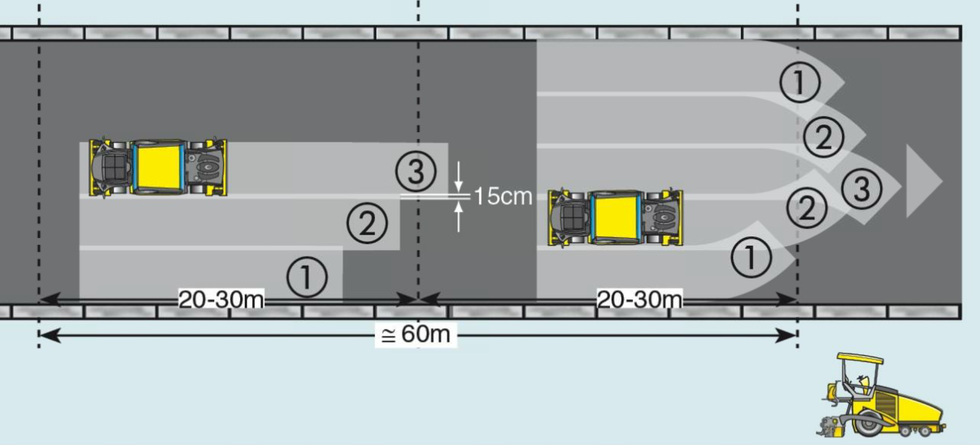
Figure 1. The paving widths and depths in Europe are often wider and thicker than those in North America. In this example of rolling patterns, the breakdown roller has time to roll from the outside toward the center of the road in one, two, three, four passes before making a final/fifth pass up the middle of mat. Notice the example in the section closest to the paver shows the slight turn the roller makes prior to stopping and reversing on the hottest portion of the mat. This slight turn helps eliminate the “hard stop” that pushes the hot mat and creates a bow of material for the roller to smooth out in future passes. The operator also turns off vibration about one roller length prior to stopping—at least 8 to 10 feet prior to stopping—to prevent breaking aggregate or creating a huge divot at the stop mark.
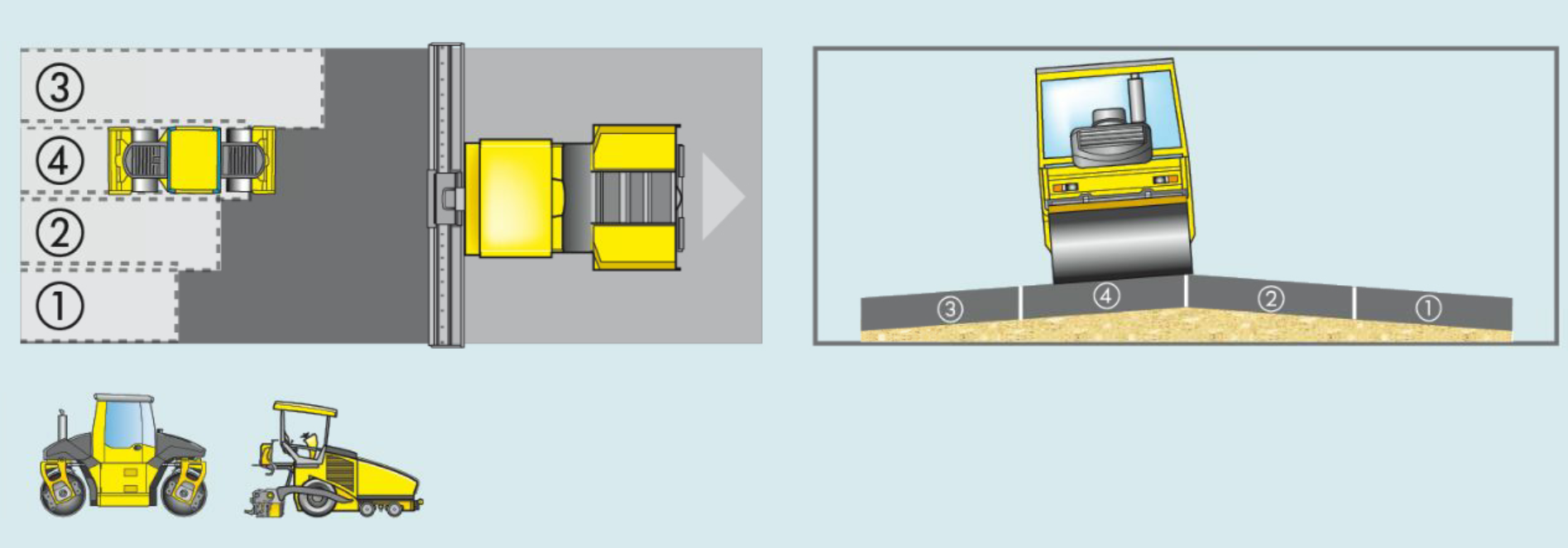
Figure 2. In this example of a rolling pattern, notice that the machine rolls from the low side to the high crown in the middle of the lane. Also notice that the roller operator isn’t letting the paver get too far ahead. To complete Pass One, the operator first rolled to a gentle stop when the roller was within about 50 feet of the paver, turning off vibration about one roller length prior to stopping. Then he reversed. For Pass Two, he did the same. At the back of Pass Two, the operator crossed on the coolest part of the mat to the other side of the lane, and then performed Pass Three, rolling to a gentle stop when the roller was within about 50 feet of the paver. Now we see the machine performing Pass Four. It will come to a gentle stop within about 50 feet of the paver, turning off vibration about one roller length prior to stopping, before reversing to the cooler portion of the mat and crossing back to the low side to begin Pass One again.

Develop Your Best Rolling Pattern

Part 2. Influences
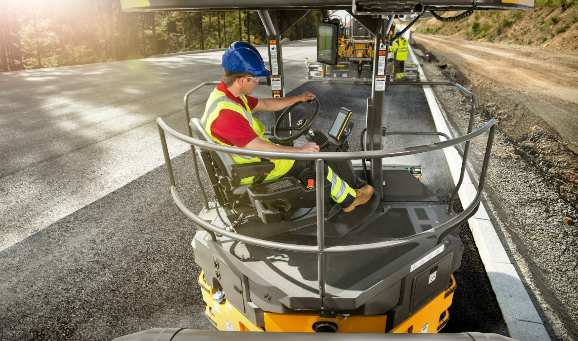
The QC tech and roller operators will determine the rolling pattern before the job starts. The intelligent compaction (IC) system helps the operator track his passes. Depending on the system, it may offer a reading or level of mat stiffness under the drums or other way to assess compaction. Photo courtesy Volvo Construction Equipment, Shippensburg, Pennsylvania.

The QC tech and roller operators will determine the rolling pattern before the job starts. The intelligent compaction (IC) system helps the operator track his passes. Depending on the system, it may offer a reading or level of mat stiffness under the drums or other way to assess compaction. Photo courtesy Volvo Construction Equipment, Shippensburg, Pennsylvania.

“No matter what size drum you have, the impactment spacing is crucial,” Ball emphasized. If the mix is delivered at a temperature less than 300 degrees F, and ambient temperature is falling, you may need to increase impactment spacing so you can increase working speed to keep up with the cooling mat. Let’s take a look at how that works.
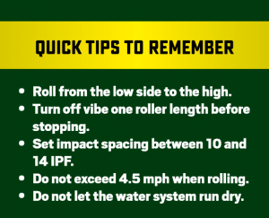
Look at what’s affecting the mat.

  1. Subbase
  2. Mix design
  3. Material temperature
  4. Lift thickness
  5. Ambient conditions (temperature, wind speed, shade from overhead)

First, the condition of the subbase is more complex than this article will go into. For this article’s purpose, let’s assume that the subbase was built to specifications and compacted perfectly. It’s dry and ready for the asphalt layers you’re placing.

Second, learn about the mix you’re placing. Chuck Deahl, formerly of BOMAG Americas Inc., has told us time and again that the temperature of the mix will influence its workability and flexibility. Tim Murphy of Murphy Pavement Technology Inc., Chicago, has told us that the more coarse the mix, the more quickly it will cool. That means you want to be on it, chasing compaction quickly.

Let’s think about the stone matrix asphalt (SMA)—or boney mix—and what curve balls it can throw at the roller operator. Ray Brown, Ph.D., director emeritus at the National Center for Asphalt Technology (NCAT) talked to us specifically about draindown, which you will look for on the new mat before rolling.

“Draindown can occur when storing the mix in a silo or when hauling the mix to the job site,” Brown explained. “Draindown occurs due to the low surface area of the aggregate and can result in bleeding in the surface of the pavement.”

One of the ways the team solves the problem of draindown is to call the plant. The operator will modify the mix with the addition of fibers or the addition of a polymer to the binder, Brown explained. Fibers are typically the answer. “If draindown is occurring, it may be that the fibers are not being properly fed into the mix,” Brown said. “Steps should be immediately taken to adjust the mix to solve the problem.”

That fixes the problem at the source, but leaves the roller operator and QC tech looking at a wet area of excess binder on the mat. Brown described it as “similar to bleeding or a fat spot.” If you roll this area, the fat spot becomes permanent and friction at that spot is lessened. Instead, Brown recommended you let the area of high asphalt content “rest” for one to two minutes.

“If draindown occurs, but is minimal and in localized spots, it is possible to let the mix set for a little bit before rolling, and the asphalt can be absorbed by the mix, thus removing the binder from the surface…If they let small draindown areas set for one to two extra minutes, the excess asphalt in these areas may drain below the surface.”
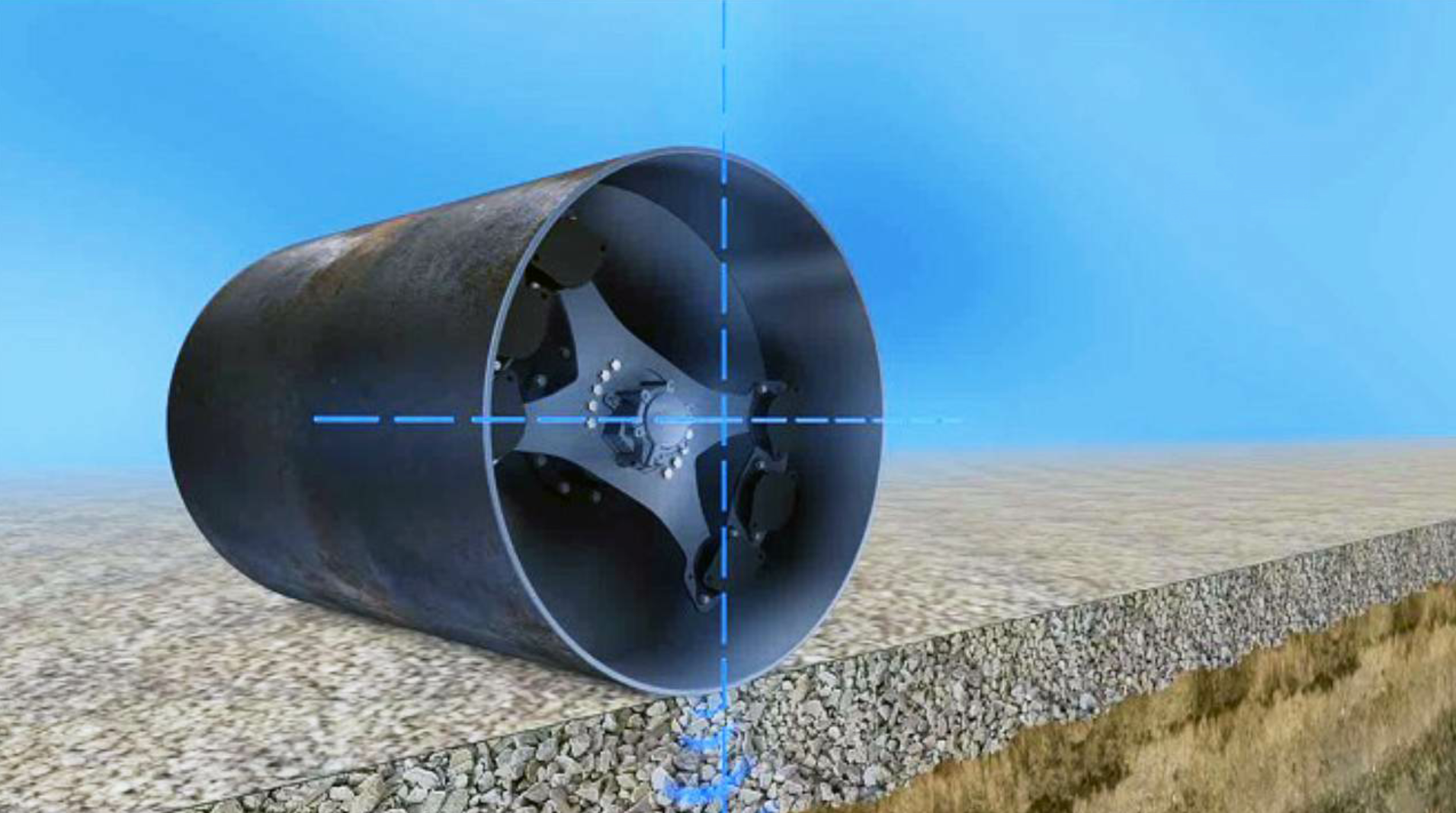
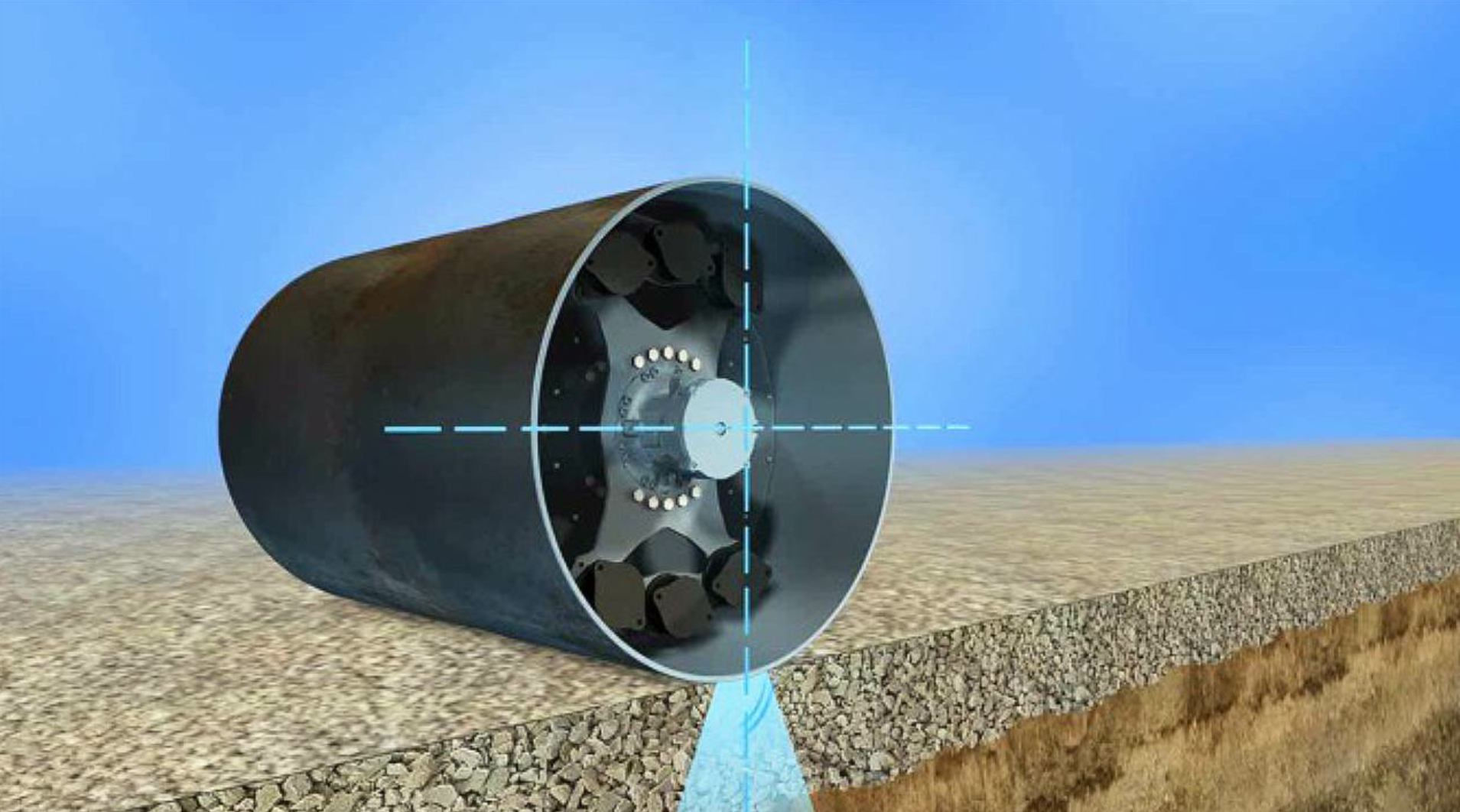
The illustration on the left shows the technology inside a vibratory drum. The mechanism within allows the drum to “jump up and down” and impact the pavement. The illustration on the right shows the technology inside an oscillatory drum. The mechanisms within allow the drum to stay in contact with the pavement while massaging the new mat. Illustrations courtesy Hamm, Antioch, Tennessee.

The illustration on the left shows the technology inside a vibratory drum. The mechanism within allows the drum to “jump up and down” and impact the pavement. The illustration on the right shows the technology inside an oscillatory drum. The mechanisms within allow the drum to stay in contact with the pavement while massaging the new mat. Illustrations courtesy Hamm, Antioch, Tennessee.

Third, waiting one to two minutes will feel like an eternity when you’re monitoring temperatures. Any rolling instructor worth his salt will tell you compaction depends on time and temperature. Let’s look at a way you can trick the roller into giving you a little extra time to work with: release agents.

During the morning meeting, the compaction team will have discussed what influences the roller settings, including mix design and material temperature. For example, if the job calls for a polymer-modified asphalt (PMA), the temperature of the mix will probably be 40 to 50 degrees greater than typical paving temperatures. A number of veteran operators suggest putting up to 20 ounces of Dawn dishwashing liquid (or up to 25 ounces of Downy fabric softener) in the water tank to assist in drum lubrication to prevent pickup of the stickier-than-normal mat.

Then, the breakdown roller operator will watch how closely he can roll to the screed. “He may be able to roll a little closer to the screed when he uses the lubricating additive,” Ball said.

For typical rolling patterns, Ball reminded operators that it’s generally acceptable to roll within 50 feet of the screed, which equals about two lengths of the paver. This allows the drums to heat, stay hot and get good compaction of the mat.

When working with a mix that exceeds 320 degrees F at delivery, Ball said it’s generally not acceptable to get that close to the screed. The danger of picking up material and leaving divots in the mat is too great because the mat is too hot; you’re using too much water for lubrication, which results in ribboning. When you add a release agent to the tank, the amount of water use lessens and the roller can get a little closer to the screed where the mat is still hottest. This takes a seasoned operator who is paying attention to make the right call.
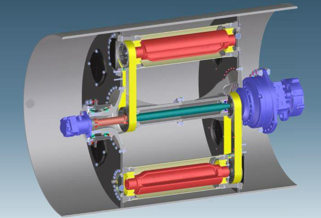
Bomag’s rendering of the oscillation technology shows the two mechanisms (in red) that cause the drum’s compaction energy to be directed tangentially into the mat. Illustration courtesy Bomag Americas, Ridgeway, South Carolina.

Bomag’s rendering of the oscillation technology shows the two mechanisms (in red) that cause the drum’s compaction energy to be directed tangentially into the mat. Illustration courtesy Bomag Americas, Ridgeway, South Carolina.

Fourth, watch the way lift thickness affects cooling of the mat and aggregate structure. Roller operators may not be well-versed in mix design specifics, but there’s a simple concept here: a thin lift that is only half an inch “tall” cannot have in it rocks that are one inch “tall.” Also, a thin lift that is only half an inch thick will cool more quickly than a lift that is two or three inches thick. These are pretty basic facts, but they’re something new roller operators may not have been introduced to yet. It’s worth taking time to share the foundation for understanding.

“Thinlays will cool quickly due to the reduced thickness of the mix,” Brown shared. “So it is important to roll this mix quickly before it cools. Sometimes higher roller frequency and lower amplitude is used for thinlays. Vibratory rollers and rubber tire rollers are effective for rolling thin asphalt layers but be careful that excessive breakdown of the aggregate does not occur. Reduced amplitude and higher frequency should help to reduce aggregate breakdown.”

Fifth, keep track of elements beyond the mat. Ron Berube of TransTech Systems Inc., Latham, New York, told readers to watch ambient temperatures and delivery times.
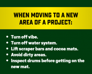
“You don’t want 10 or 12 trucks sitting there cooling,” Berube said. He pointed to the use of material transfer vehicles (MTVs) to remix material and bring temperatures back to optimum. “Odds are, if they’re using an MTV, they’re not having any issues,” Berube said. “They really have to look at the overall process of laydown. They may be paving too fast for the breakdown roller to get on the mat. If they know what mix they’re using at the beginning of paving and get their settings locked in, things generally won’t fall apart.”

Berube said paving speed often turns out to be the problem. It’s a fact that contractors often find themselves trying to keep up with production or a line of trucks; this makes it difficult to slow down a paving train. “Usually the problem is that they’re paving too fast for the ambient temperature,” Berube said. “If they just can’t slow down, they may have to adjust the pattern. They may have to eliminate the static pass for the breakdown roller. Or they may run a second breakdown. The ambient temperature will affect the speed at which you pave and get compaction.”

His colleague, Morse, agreed, saying, “The production speed at the plant affects this, too.” If the plant loads out all the tons that have been stored first thing in the morning, and then begins producing tons, watch production temperatures and delivery times. Fluctuations will affect what the haul truck brings to the paver.

“It’s a big team out there,” Morse said. “You need the team leader out there, the density tech.”

Develop Your Best Rolling Pattern

Part 3. Your Secret Weapon
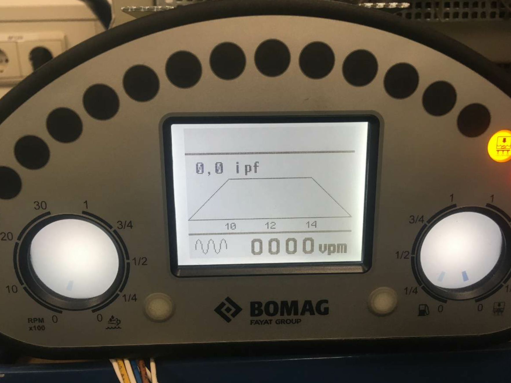
Impactment spacing should be set between 10 and 14. Photo courtesy Bomag Americas, Ridgeway, South Carolina

Impactment spacing should be set between 10 and 14. Photo courtesy Bomag Americas, Ridgeway, South Carolina

Ball calls the pneumatic tired roller your secret weapon. For this machine, it’s all about the tires. You achieve compaction with the pneumatic roller through contact pressure. Of the two types of tires—radial and bias—to choose from for this piece of equipment, the bias tire, will provide full contact with the mat.
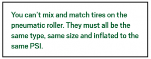
You will give special attention to the tires in your daily walk-around of the machine prior to shift start-up. You want to make sure they’re smooth, not cut up with canvas showing. Depending upon the size of the tire, and how much of the tire needs to stay in contact with the mat, you have the option for each tire to be between 50 and 120 PSI.

For example, a tire which is 750 x 15-inch, 20-ply, radial on a 10-ton roller might require 50 PSI, if you’re laying a 1-inch lift; or 75 PSI, if you’re laying 3 inches. (Ball explained this isn’t the Gospel; it’s a range.)

A 10-inch wide bias tire on a 10- to 25-ton roller may require up to 120 PSI. Your dealer can tell you the specifications for your model’s tire.

Now here’s a tip for keeping tire pressure even throughout the shift. Keep the temperature gun handy. When double-checking mat temperature to make sure you’re getting into the rolling zone at the right time, also take the temperature of the tires. Check each one individually. If one reads lower than another (80 instead of 120), it’s flat. It has low pressure and it needs to be reinflated. These days, OEMs include compressors on the operators’ platforms, so you can adjust pressure more easily in the field. The QC tech will make the call if contact pressure needs to be changed in all tires. As Berube mentioned earlier, once settings are in place at the beginning of the shift, big changes shouldn’t be necessary.
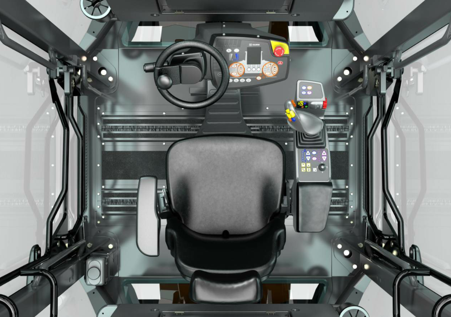
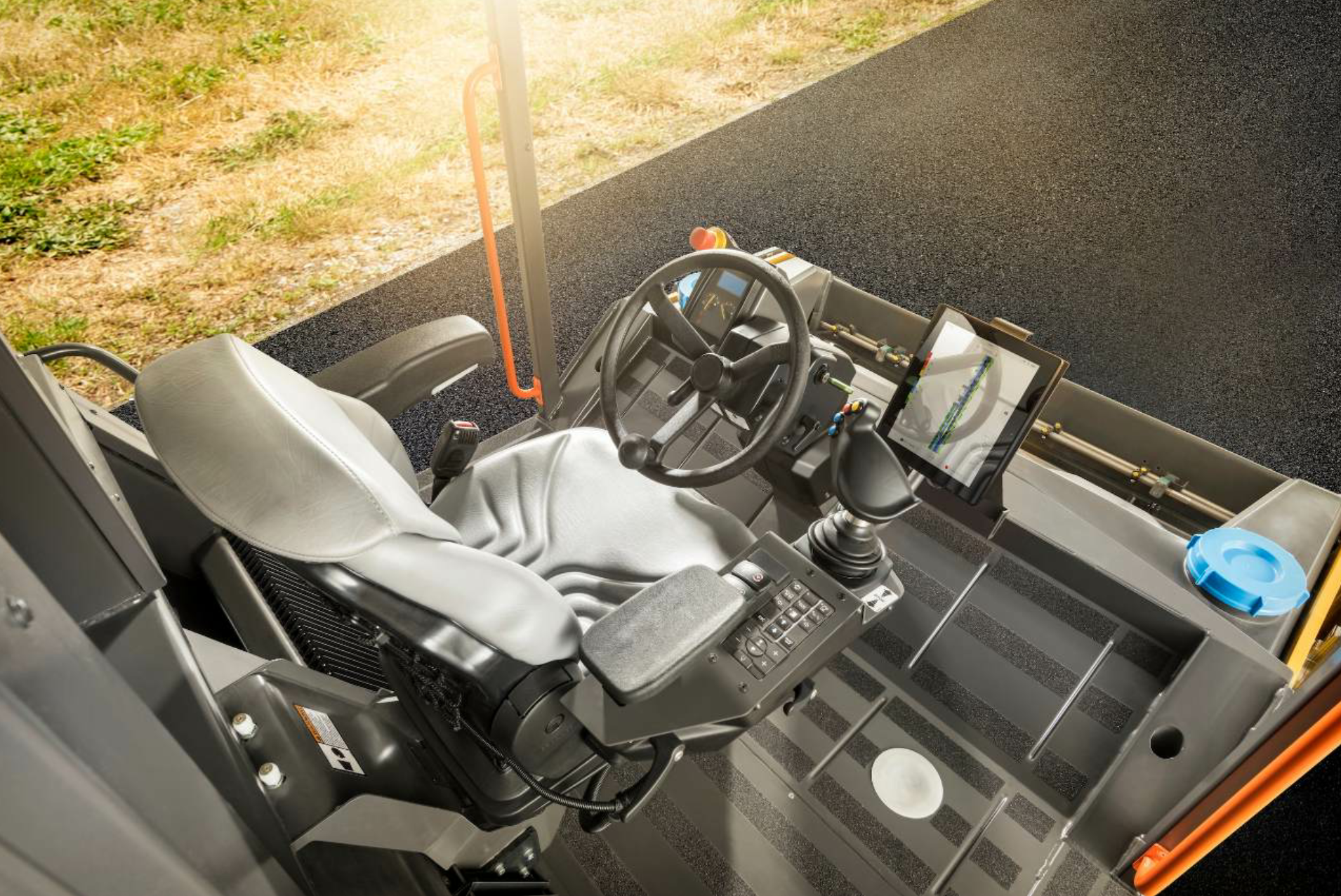
The Hamm Compaction Quality (HCQ) system features a color touchscreen PC with USB interface at the operator’s station. The setup in the cab is designed for operator comfort with steering accomplished via steering wheel and controls via a joystick and armrest. Photo courtesy Hamm, Antioch, Tennessee.

The Hamm Compaction Quality (HCQ) system features a color touchscreen PC with USB interface at the operator’s station. The setup in the cab is designed for operator comfort with steering accomplished via steering wheel and controls via a joystick and armrest. Photo courtesy Hamm, Antioch, Tennessee.

Getting into the pneumatic roller’s operation, we see that its tires are not as forgiving as the steel roller’s drums are. For example, if you roll onto a portion of the mat that is too hot for the cool tires, they will pick up material, as the cool drum would. But the tires will start wrapping the material around them, grabbing more and more, creating a mess of the mat, according to Ball. One way to guard against this mess is to use lubrication on the tires until they are heated up and staying hot. Staying hot means you’re not stopping on the coolest part of the mat for a break. “Most rubber tire rollers have two tanks now—one for water, one for a release agent. He can use lubrication when he first starts…until the tires get up to temperature.”
Volvo’s Density Direct features an 8X10 touch screen display and uses a GPS to track roller passes. Photo courtesy Volvo Construction Equipment, Shippensburg, Pennsylvania.

Volvo’s Density Direct features an 8X10 touch screen display and uses a GPS to track roller passes. Photo courtesy Volvo Construction Equipment, Shippensburg, Pennsylvania.

The pneumatic tired rollers are built to withstand any temperature, depending on the ply of the tire. Remember, the higher the ply, the stronger the tire. Considering the pneumatic tired roller will likely operate in the intermediate position, it should not experience the hottest temperatures of the mat. Be aware of temperatures and limitations; discuss these limitations of where you can and cannot go in the rolling zone during the rolling train quality control meeting. For paving in windy or shaded areas, or during times of the year when temperatures drop during the latter part of the day, you’ll want to have a skirt around the tires to hold heat evenly against them.
The intermediate roller is responsible for achieving about one percent of density, according to Ball. To succeed, you have to be “in” the right time and temperature. Be aware of the time and temperature of your rolling zone, which will depend on the type of mix you’re working with, the thickness of the lift, paving speed, and a host of other variables. Depending on whether you’re working with an HMA or WMA, there’s no telling just what temperature defines the intermediate zone for your project on a given day. That will be determined during the compaction team meeting.

Also, depending on the mix you’re working with, you may need to take the pneumatic roller out of the compaction train. Brown gives tips for the SMA mix, specifically. “Rubber tire rollers are typically not used on SMA mixes,” Brown shared. “Some states use vibratory rollers and some do not allow vibratory rollers to be used due to potential for breakdown of aggregate. When steel wheel rollers, especially vibratory rollers, are used, ensure that excessive breakdown of aggregate does not occur underneath the rollers.”

Use Your Intelligence
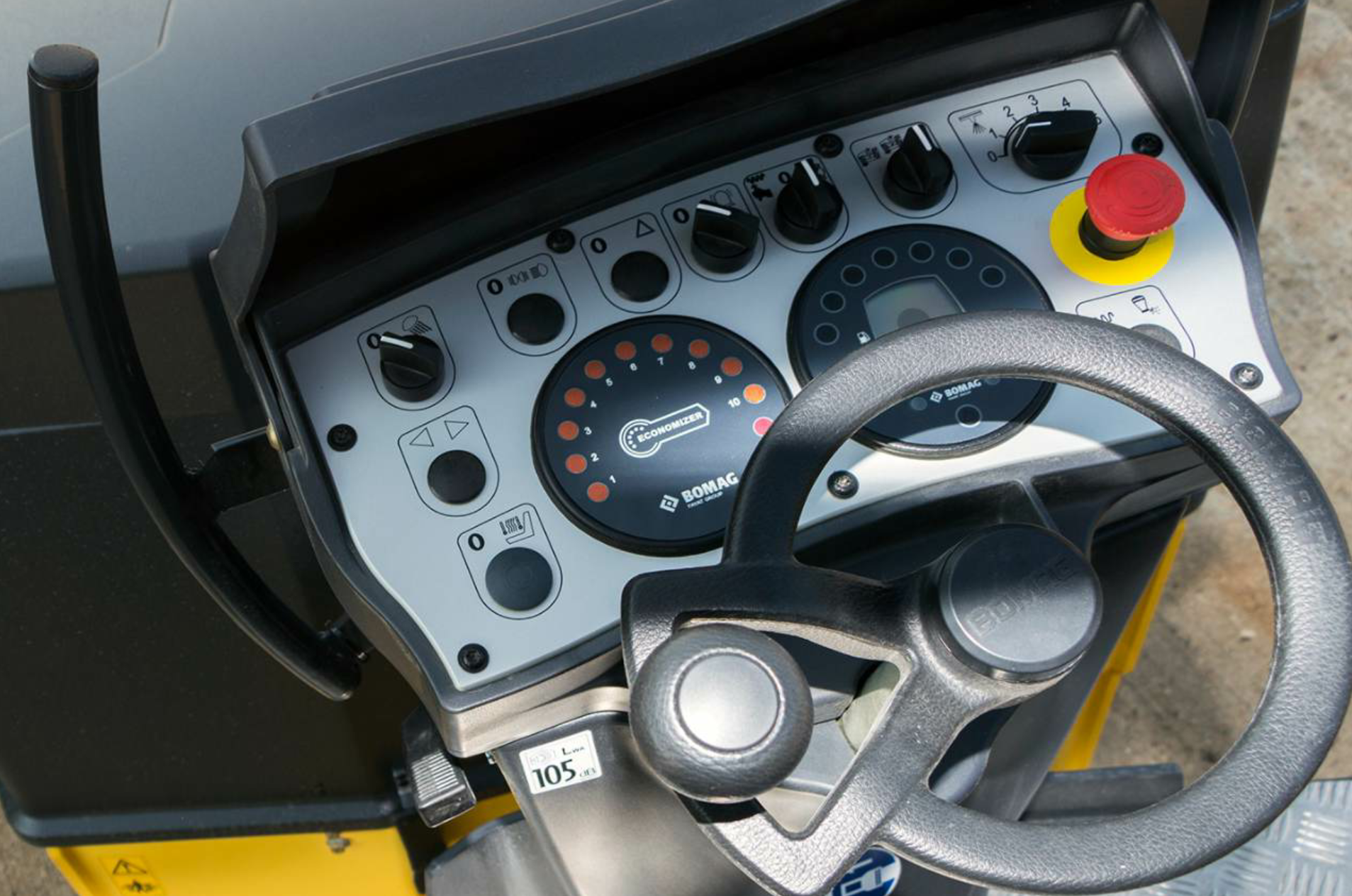
BOMAG Americas’ Economizer, available for any compaction equipment, features a dial display at the operator’s station and uses a monitoring device to track mat stiffness. Photo courtesy Bomag Americas, Ridgeway, South Carolina.

BOMAG Americas’ Economizer, available for any compaction equipment, features a dial display at the operator’s station and uses a monitoring device to track mat stiffness. Photo courtesy Bomag Americas, Ridgeway, South Carolina.

Continuing advances in intelligent compaction (IC) and in-cab comfort designs for operators make it easier for members of the compaction train to do their jobs well. As Ball mentioned earlier, it’s more of a numbers game now than it used to be. State projects are awarded bonuses or penalized with deducts based on the percentage of density you achieve on the mainline and at the longitudinal joint, and on ridability.

For a quick review of the top OEMs’ IC packages, here are some options, in alphabetical order:

  • Atlas Copco’s intelligent compaction system features a touch screen display at the operator’s station and uses a GPS to track roller passes. It is designed to measure the surface’s relative material stiffness. For more information, visit www.atlascopco.com.
  • BOMAG Americas’ Economizer, available for any compaction equipment, features a dial display at the operator’s station and uses a monitoring device to track mat stiffness. It is designed to measure mat stiffness. For more information, visit www.bomag.com.
  • Caterpillar’s Cat Compaction Control can be configured with a color display at the operator’s station and GPS mapping technology to track roller passes and coverage. It can also be configured to measure mat temperatures and provide a composite indication of the stiffness of the mat, sub-layers and potentially the base. For more information, call on a local Cat dealer.
  • The Hamm Compaction Quality (HCQ) system features a color touchscreen PC with USB interface at the operator’s station, and uses a proprietary, subscription-based OmniSTAR HP system, which provides location precision of 2 to 4 inches directly from differential global navigation system satellites operating in real time to track roller passes and record mat temperature and stiffness. For more information, visit www.hamm.eu/en/technologies/hcq/.
  • Sakai uses CIS2 from Topcon, available on Sakai machines only, which features a touch screen display at the operator’s station and uses a VRS network to track roller passes. It is designed to measure the surface’s relative material stiffness. For more information, visit a local Sakai dealer.
  • Volvo’s Density Direct features an 8X10 touch screen display and uses a GPS to track roller passes. For more information, visit www.volvogroup.com.

Ball reminded readers that these systems are not overly difficult to use once the operator gets the hang of it. The complexity usually goes on “behind the scenes,” so to speak. Even though the controls are designed to be user-friendly, the OEM’s dealer needs to explain the system to the operators until they understand it. The IC does no good if the operator turns it off, or changes the settings without understanding how they affect the mat.

For example, on a bridge project where Ball consulted this past summer, getting density required working without vibration. He worked with the team to lease a set of rollers with Bomag’s oscillation technology—TanGO—and Bomag’s IC system—Economizer. Ball worked with the QC tech on the job to set the adequate settings, and the compaction team went from failing with 89 percent densities to achieving the required 96 percent densities with two passes. The next day, Ball noticed density declining to 92 percent on one of the rollers when he and the QC tech checked numbers with TransTech’s PQI gauge. He went to the roller to discover the operator—who had only been rolling for about five months—had changed a setting; the operator had dialed the setting “back” because he misunderstood the difference between vibration and oscillation and misunderstood how his actions would affect the mat.

As the training consultant, Ball had the opportunity to teach the green operator about these elements, and density returned to 96 percent. This kind of misunderstanding happens with veteran operators, too, if new technology appears without instruction. The best way to leverage new technology such as IC is to ensure your equipment operators know how to use it for bonus pay.

Finishing Marks

As you can see from that example, the roller operator needs understanding when setting the rolling parameters. When the QC tech starts the day with the compaction team meeting, he will share more than what settings to dial in for each roller. He’s going to share the what, why and how to get density numbers and smoothness for the job.

Don’t forget to take time to know your compaction equipment. As discussed in the September issue’s first part of this series, the rollers take routine and special maintenance. And as we see in this part of the series, the rollers need ongoing attention during the shift to make sure they don’t run out of water or fuel, to make sure the drums are lubricated, to ensure tires—or drums—stay hot, and to keep scraper bars and cocoa mats in good condition.

The list seems endless, but becomes second nature as the equipment operators mature and grow more familiar with their machines. When you take the time to know your equipment and know how to apply your equipment to the job at hand, you can get a good result. The rolling team that works together to learn and understand the elements of compaction is the team that will complete a bonus-worthy job.

Asphalt Test Track in Germany Tests Asphalt Strength

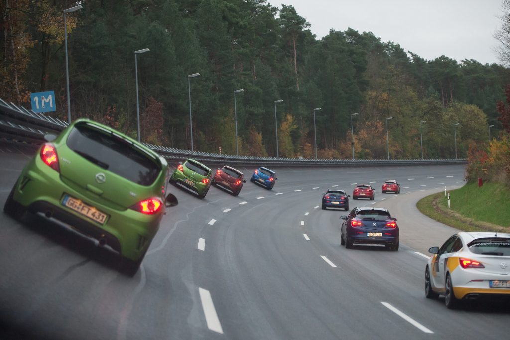
Car manufacturers use specially built test tracks to develop new vehicles and to test vehicles already in production. Many different track sections are needed such as uneven “torture tracks” and high speed tracks with a very smooth surface. In 1919, Opel built its first test track. Rides with a maximum speed of 87 miles per hour (140 kph) were possible on the concrete oval of almost 1 mile (1.5 km) in length close to Rüsselsheim, Germany. A bigger testing ground was constructed 1951 within the factory premises of Rüsselsheim, but it proved too small after a very short time.

Therefore, in 1964 Opel started the construction of a new testing ground in Rodgau-Dudenhofen, a small city in a woodland south of Frankfurt. Part of this new test area was a high speed course. In 1993, it was completely rehabilitated, including the subbase.

Refine with Asphalt

When Concrete Fails

In 2012, the track was renewed again and technically refined. That’s where this article begins. For this project, the track was milled and a new, strongly superelevated asphalt surface with no longitudinal joints was paved. At the same time, it was re-profiled to allow even higher car testing speeds.

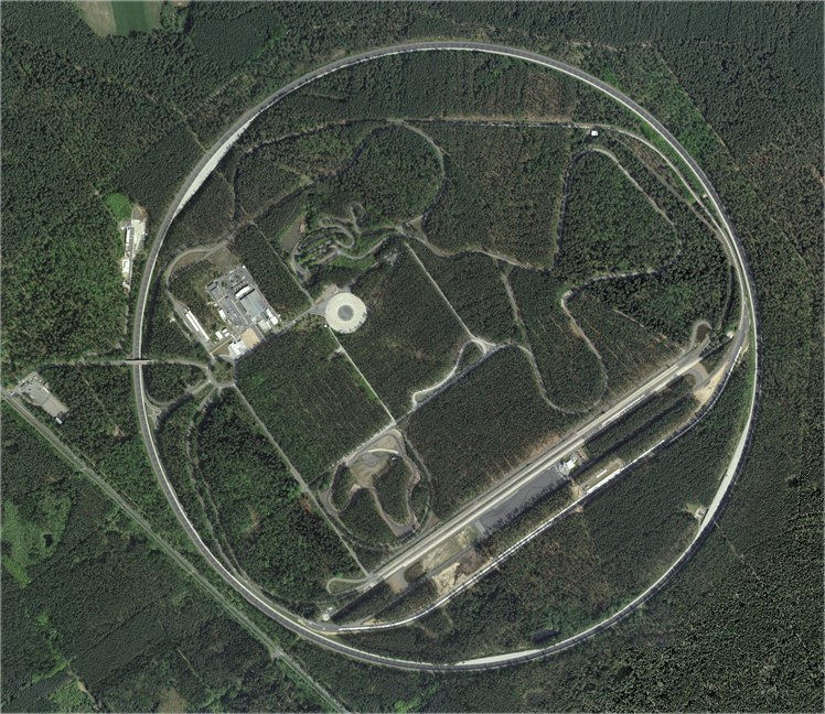
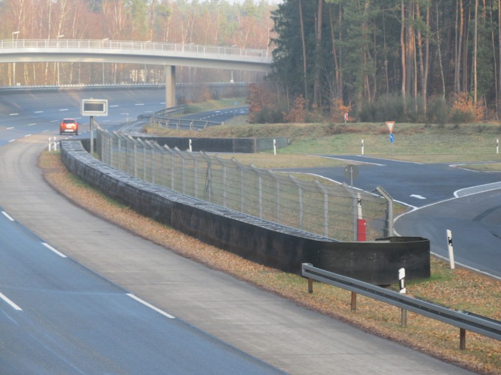
The Testing Center of the Adam Opel AG is surrounded by a circular high speed track of almost 3 miles (4.8 km). The shape of the track corresponds to an infinite straight line. That means that constant rides without side acceleration and nonstop-rides with defined operating conditions can be realized. Initially, this circuit was made of concrete with three lanes, parabolically superelevated, with a total width of 46 feet (14 m) and a radius of almost 2,500 feet (760 m). The cross slope of up to 32 degrees allowed a maximum speed of 140 mph (225 kph) without side acceleration. Six brake stops for braking tests, constructed in concrete, were located along the circumference at the inner part of the track.

Shortly after the completion of the track, defects occurred on the concrete surface at the end of the daily paving sections. Subsequently, many blow ups occurred in the following years. The smoothness worsened, the track became bumpy and the accuracy of test results suffered accordingly. The damages were mainly traced back to a bad compaction of the subbase, a poor joint maintenance, an intense use of salt during winter services, and a malfunctioning drain on the inner curb of the track. This resulted in a complete rehabilitation of the high speed track and in a reconstruction of the drainage lines on the inner curb of the track in 1993.

Within only five months, the old concrete track was broken down and recycled, the entire subbase was renewed and a hydraulically reinforced base course of 0.5 foot (15 cm) was built. In doing so, the maximum cross slope of the track was increased to 37 degrees. The three outer lanes were now paved in asphalt. The inner lane for brake tests and slow rides was made of concrete including three special concrete brakepoints. A supply and maintenance road was installed outside the track on the top of the embankment. To improve safety, two sign gantries with driver information system as well as a road illumination were added.

The construction of the lanes was carried out according to the German technical guide lines (ZTV bit-StB 84/90 and ZTVT-StB 86/90). For the upper asphalt layer, an extra stable mix using the plastomer Vestoplast as a binding agent was used. Basalt and diabase chips were employed as mineral compounds. That was 1993. Twelve years later, cracks happened.

From 2005, cracks occurred in many areas of the track. Therefore experts from the road and pavement engineering sector of TU Darmstadt examined the track. They suggested an obvious hardening of the binder was to blame. The influence of the used binding agents was discussed as another reason, but not pursued. The cracks in the track surface allowed water, thawing chemicals and oxygen into the construction, which intensified the aging process. At this time, the concrete track and the three brakepoints showed no damages. Also the joints including their tapes were almost in good condition, too. So the tasks for the rehabilitation of the high speed track in 2012 were as follows:

  1. Dismantle the road installations such as guard rails, sign gantries, metrology instrumentation, ductwork and other electrical installations
  2. Mill and re-profile the asphalt surface and binder courses of the complete track;* mill the surface course of the framing supply and maintenance road
  3. Repair the base course in the areas damaged by top-down cracks
  4. Pave a new asphalt binder course and surface course
  5. Reassemble road installations and complementing metrological devices

Upgrade the Curve

The Adam Opel AG wanted to change the curve profile in a manner that a speed of 155 mph (250 kmh) without side forces would become feasible. As with a total thickness of 8.7 inches (22 cm), the existing three-layer asphalt construction from 1993 was over-dimensioned for the load of passenger cars, the project team decided to give the track a new, steeper profile by milling. Therefore, they milled the surface course, the binder course and 1.2 to 1.6 inches (3 to 4 cm) of the base course in the central part of the cross section. In addition, they over-profiled the outer third, thereby increasing the maximum cross slope on the upper edge of the track from 37 to 40 degrees.

The high speed circuit is part of nearly every test routine in the Test Center Dudenhofen. It is highly frequented, thus needed an extremely short construction time. Construction was scheduled for the period from mid-January to the end of June 2012. For the asphalt paving an experienced team with a special paver and special rollers was essential. The paver had to produce three lanes with parabolic cross section without longitudinal joints in one flow of work. The SMB Construction International GmbH, a collective subsidiary company of the Strabag International GmbH and the Max Bögl group of companies, was awarded the project as a prime contractor. The research center for road and pavement engineering of the TU Darmstadt and the engineering office Hart Consult International GmbH under the direction of Dr. Rainer Hart were responsible for the quality control.

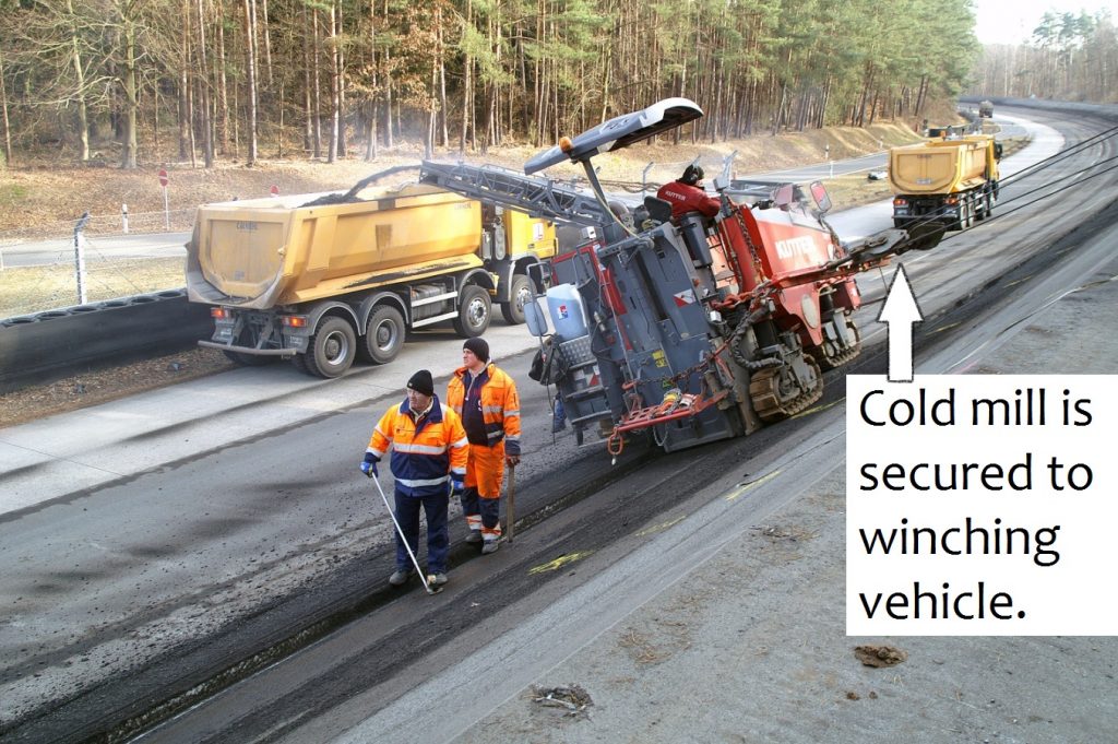
After the dismantling of the guard rails, a cold milling machine with a cutting width of 1 m removed the asphalt surface course and binder course, as well as parts of the asphalt base course on the entire high speed track, which is about 621,600 square feet (57.750 m²). The average milling depth was approximately 4.7 inches (12 cm). The milling was done counterclockwise. For the purpose of pre-profiling the new slope and to comply with the minimum thickness of the remaining base course, the milling depths were given in sections and checked directly behind the milling machine. Finally, a high-pressure water jet and a rotating broom were used to clean the milled area.

After the surface and binder course were removed, the repair and maintenance works were mainly carried out manually. The damaged, non-stable areas of the base course were milled; non-fixed or loose layers were loosened, washed away and cleaned. The new base course was built manually in these areas. Moreover, cracks were widened out, cleaned and grouted.

The asphalt layers were paved daily between 6:30 a.m. and 8:00 p.m.; therefore, the paver was prepared starting 5:00 a.m. Approximately 2,000 feet (600 m) of asphalt lane was paved per day. The daily joints of the surface course were always positioned offset to the daily joints of the binder course.

The project team turned their attention especially to the formation of the upper edge of the high speed track. The joint between the layers of the test track and the supply and maintenance road was designed in a special way to prevent water from entering the binder and the surface courses through this area.

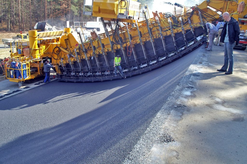
The required asphalt track with parabolic cross section and without longitudinal joints was built by means of the bridge paver from SMB Construction. This machine was designed especially for paving circuits and tracks with curved and superelevated profiles and changing radii. The asphalt mix is transported from the truck by means of a self-propelled feeder and adjustable augers to a scraper belt. A paddle chain then distributes the mix evenly in front of the screed. A microprocessor-based controller in the paver takes care of the correct position of the screed elements. Contact-free inductive sensors—joint matchers/trackers—measure both position and height, from specially developed reference rails—skis. Then, the computer controlled hydraulic cylinders deform the screed in a way that the paved layer reaches its nominal position in each area of the space curve. The data needed was exactly determined in advance and stored in the paver’s software as a digital terrain model. Simultaneously, a slope control system surveyed the inclination of the bridge girder. In parallel, a surveying team checked and recorded the paving continuously.

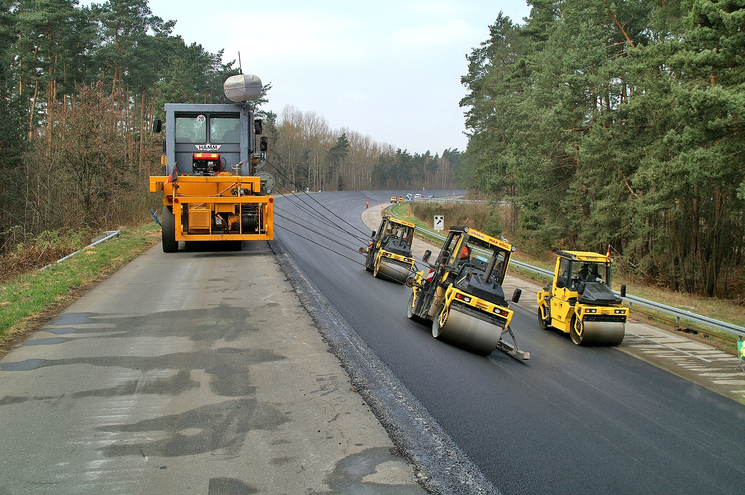
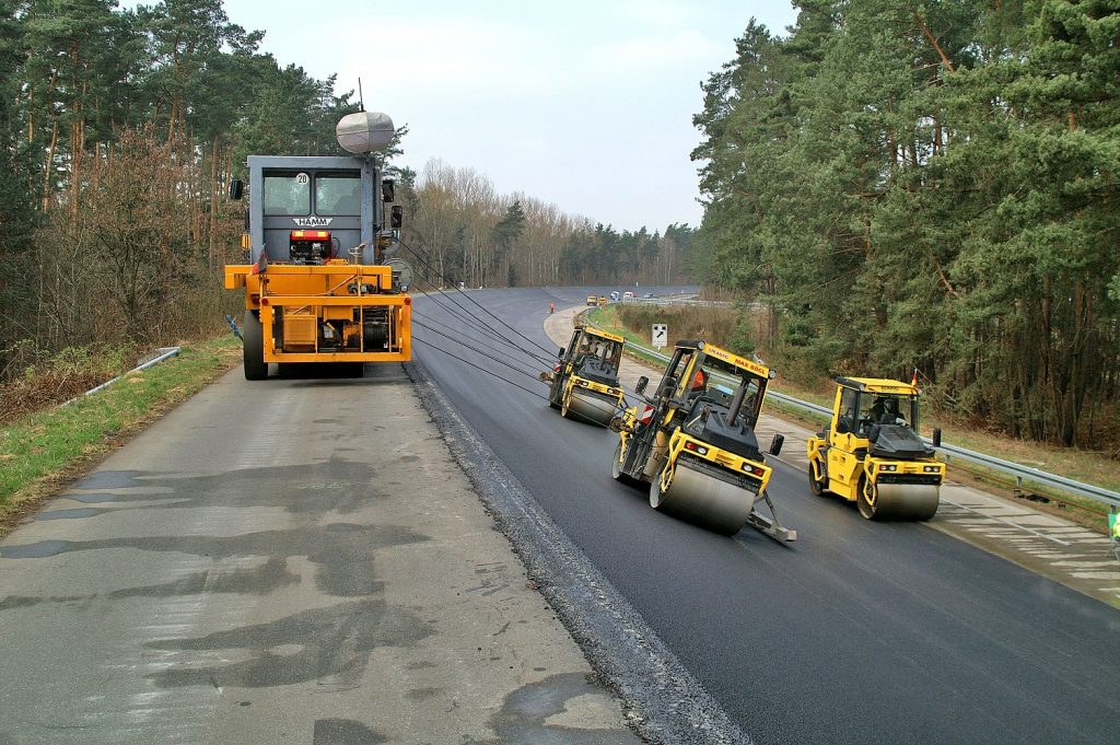
For the compaction, double vibratory rollers with specially shaped drums were used. Moreover, two rollers in the upper, steep area were each lead by a mobile winching vehicle. The roller in the shallower track section worked without winching vehicle. The use of a roller lead by a winch brings a considerable time frame of approximately 15 minutes between the paver and the breakdown compaction. This is why it might become difficult to achieve the intended degree of compaction under poor weather conditions such as low ambient temperatures or strong winds. This problem is worsened by the inclination in the top section because the rollers necessarily develop lower normal forces and thus a lower compaction effect.

Sensors were integrated into the new road surface. They permanently deliver data concerning temperature and humidity of the pavement so that these could be considered both in the testing results and to detect the road characteristics. Moreover, the new safety barrier on the upper edge was “electrified.” It was equipped with signal transmitters, which are able to inform the drivers on the track in case of an impact.

Mix It Up

Adam Opel AG demanded a long-lasting asphalt pavement with homogeneous surface. In addition, paving in steep slope required an adequate stability of the asphalt in hot, non-compacted condition.

An asphalt concrete AC 16 BS with a 4 percent void content served as binder course and repair material. As the low air voids constrain the bitumen’s natural aging process, the mix should be especially long-lasting. The use of hydrated lime as a filler stiffened the mix in hot state and had a positive influence on the asphalt layers’ weathering resistance.

A stone mastic asphalt SMA 11S, which was mixed with low void content and low tendency for segregation, was used for the surface course. As binding agent, a highly modified special bitumen was used, which, being a polymer component, not only contained SBS-elastomers, but also contained plastomers to effect better compactibility under low temperatures. The binding material’s chemical affinity to the stone was increased using a fiber additive.

Compared to the official standards, the requirements for the aggregate were increased with regard to their polishing resistance, shape, impact resistance, and the admissible over- and undersize. Moreover, the construction contract radically limited the road-building related tolerances to be found in the official standards (ZTV-Asphalt); most of the parameters were restricted to half of their value. Further parameters, such as the void filling level, were taken into the catalog of requirements and given tolerances. Some of the suppliers did not believe those requirements to be practical, thus did not submit bids. Table 1 shows some details of the spec.

In vehicle development, the test track works as a measuring system whose performance characteristics have to remain constant even over years of intensive use. This results in quality requirements beyond the standard monitoring in road construction. In particular, the steep slope of the track requires a constant asphalt consistency. Due to significantly higher costs compared to usual road construction, the risk of failure is to be minimized. This being said, an internal and external monitoring team with a site lab was installed to support the construction. Their tasks included:

  • Preparing measures (internal and external monitoring to be agreed upon)
    Exploration of suitable occurrence and suppliers for the aggregates, sampling of relevant quarries, definition of the extraction areas, sampling and optimization of the minerals processing, determination of suitable binders, inspection of different asphalt mixing plants, selection of an adequate plant close to the location and comparative analysis of the internal and external monitoring
  • Optimizing the mix proportion
    Extensive initial inspection (variation of binder contents included), verification of cold behavior and water sensitivity, calibration of the mixing unit, sample mixes, test the mix proportion and the compression regime in testing fields and definition of a final composition
  • Quality management supporting the construction
    Nondestructive density measurements to estimate the compaction success during the paving (e.g. in hot condition), asphalt analysis with submission of the results within 2 to 4 hours so that an immediate correction was possible, daily survey of the screened aggregate mixes at the plant and potential adjustment of the design, bitumen analysis and survey of the compaction of the installed layers on asphalt cores

The described activities were completed in only five months time. The design and construction followed the general technical basic rules, but with special machines and essentially higher demands on dimensional accuracy and compliance with the mix design. After all, this was the design and construction of a three-dimensional structure with an extreme cross slope of up to 79 percent and a longitudinal slope of 0 percent on the entire track.

The complex quality survey showed that it is certainly possible to drastically decrease the tolerances of the mix proportion against the specs of the basic rules (TL Asphalt-StB). Problems had to be solved on short notice and on-site. At the same time, it was rarely possible to build on experiences with comparable structures. This required a close cooperation of all team members as a top priority. This was the only possibility to respond to the tight schedule without quality losses. The users of the new track, the test drivers of the Test Center Dudenhofen as well as the technical group and the measuring group of the Technical Development Center of the Adam Opel AG in Rüsselsheim confirm that this project has been carried out with success.

Dr. Stefan Böhm is with the Road and Pavement Engineering, TU Darmstadt. Dipl. Engineering Martin Drees is with the Adam Opel AG. Dr. Gerhard Faust is formerly of Adam Opel AG. Dr. Rainer Hart is with Hart Consult International GmbH. Dr. Markus Limbach is with SMB Construction International GmbH.


For 2012, the Adam Opel AG wanted to change the curve profile of the track so speeds up to 155 mph (250 kmh) could be achieved without side forces. The existing three-layer asphalt construction from 1993 had been over-designed for the load of passenger cars, so the project team needed to mill off the layers and profile for a steeper finished surface.

Shortly after the completion of the track, defects occurred on the concrete surface at the end of the daily paving sections. Subsequently, many blow ups occurred in the following years.

They increased the maximum cross slope on the upper edge of the track from 37 degrees to 40 degrees.

German Paver

In this image, the bridge paver from SMB Construction lays the asphalt mix with an electrically heated screed. The screed consists of 17 individual bodies which are linked with the permanent screed plate. 17 hydraulic cylinders control the deformation of the screed; the cylinders are controlled by automation. This machine was designed especially for paving circuits and tracks with curved, superelevated profiles and changing radii. Here’s how it works:

  1. The asphalt mix is transported from the truck by means of a self-propelled feeder and adjustable augers to a scraper belt.
  2. A paddle chain then distributes the mix evenly in front of the screed.
  3. Contact-free inductive sensors—trackers—measure both position and height, from specially developed reference rails—skis.
  4. A micro-processor-based controller—automation—positions the computer controlled hydraulic cylinders to deform the screed in a way that the paved layer reaches its nominal position in each area of the space curve. (For the Adam Opel AG project, the data was determined in advance and stored in the paver’s software as a digital terrain model.)
  5. Simultaneously, a slope control system surveys the inclination of the bridge girder. (For the Adam Opel AG project, a surveying team checked and recorded the paving continuously for quality control.)

German AerialThe Testing Center of the Adam Opel AG in Rodgau-Dudenhofen, Germany, is surrounded by a circular high speed track of 2.98 miles (4.8 km). The shape of the track corresponds to an infinite straight line.German MillingFor the purpose of pre-profiling the new slope and to comply with the minimum thickness of the remaining base course, the milling depths were given in sections and checked directly behind the milling machine. Cross slopes of more than 9 degrees made a winching vehicle necessary that held the machine to enable milling in the banked track.KONICA MINOLTA DIGITAL CAMERATo avoid roller marks, the edges of the roller drums should exert no pressure on the freshly compacted asphalt. For this reason, the upper rollers were equipped with a slope control. A computer in the winching vehicle controlled the height-adjustable hold point in a manner that the rollers permanently drove orthogonally to the surface.German DrivingTire walls and safety fences ensure the safety of drivers and staff who stay along the track during the testing. After the rehabilitation, the test drivers from Opel are highly satisfied with the quality of the new track.

German Electric

Table 1: Specification of surface course and binder course

Binder Course Surface Course
Asphalt Mix Type AC 16 BS SMA 11S
Bitumen 70/100 Olexobit SMA; PmB 40/100-65 A
Softening point
ring and sphere
47.6 °C 71.6 °C
Needle penetration 81 (1/10 mm) 50 (1/10 mm)
Additives hydrated lime N/A
Void content 4% 2.2%
Technical specifications TL Asphalt-StB 07, ZTV Asphalt-StB 07 and further technical requirements

Maintain Quality in Cooler Temperatures

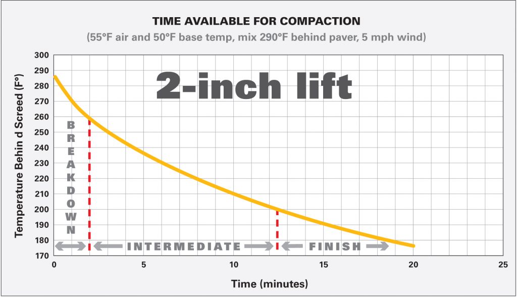
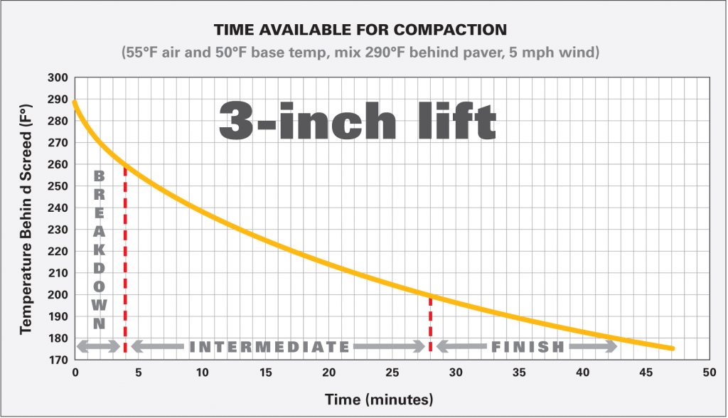
Professional contractors know how to make sure their operations are successful when cold weather arrives. They ensure quality continues. In the context of this article, quality will refer to the optimum degree of compaction achieved behind the paver. It is generally recognized that effective compaction is a critical variable in placing a quality asphalt pavement that will perform well for many years. Field experience confirms that paving can be done under adverse weather conditions; however, the key to success is recognizing which paving practices are best in the warm summer months and which are best during October through April.

The temperature of hot-mix asphalt (HMA) during breakdown, intermediate and finish rolling will determine how successful the compaction operation will be. It is important to have an understanding of how mix temperature is related to the compaction of HMA.

Get Back to Basics

We know HMA is composed of aggregate and liquid asphalt cement (AC). For the concepts in this article, it’s important to remember that the AC binder has different viscous behavior at different temperatures. At low temperatures, AC will be highly viscous. This means it is “thick,” or slow moving. At high temperatures, AC will be less viscous. This means it flows more easily at higher temperatures.

For paving applications, it is critical that the crew maintain the optimum mix temperature from the plant, through the paver, to the rollers. This is especially challenging in cold weather.

As long as the AC binder within the mix is viscous enough to “flow,” the compactive effort of the rollers can force the mix into a compacted, stable configuration with good aggregate interlock. As the temperature of the mix drops, the AC within it becomes more viscous and more glue-like. When the AC hardens, the aggregate in the hot mix cannot be manipulated into a dense configuration by the force of the rollers.

The time available for compaction is defined by the total amount of time that it takes for the mat to lose so much heat that it is too stiff to compact. The following list summarizes the primary factors influencing the rate of heat loss in HMA.

Primary factors affecting temperature loss in HMA mats

Lift thickness

Base temperature

Mix delivery temperature

Ambient air temperature

Wind speed

Solar-radiant flux

Thicker lifts hold temperature longer than thinner lifts. The heat retained in asphalt lifts is not a linear relationship, but rather an exponential one. For example, a 3-inch (75-mm) lift will retain heat for approximately four times as long as a 1.5-inch (40-mm) lift of the same mix placed under the same conditions (See Figure 1).

Base temperature also plays a significant role in how much time is available for compaction. This is especially true for thin lifts in cool weather. Heat transfer generally occurs more quickly through more dense media. For example, a glass of water will freeze much more quickly when placed in contact with ice in a bucket than when set on the middle shelf of a freezer with only cold air around it. The base material on which the asphalt is placed is essentially an infinite mass when compared to the thin lift of HMA on top. The base will absorb large quantities of heat very quickly.

Laws of heat transfer tell us that when two surfaces of different temperatures are in contact, the resulting system will tend toward reaching a state of thermal equilibrium. That’s when both materials in contact eventually reach the same temperature. This phenomenon is observed when hot asphalt is placed on a cold base. The heat, or thermal energy stored in the HMA, quickly transfers to the cold base as the system tends toward thermal equilibrium. A greater temperature differential between the two materials means that the rate of heat transfer will occur faster. For thin lifts, because there is relatively little mass of HMA, heat transfer from the asphalt mat to the base occurs quickly. Heat transfer is primarily a function of mass, temperature differential and thermal conductivity.

Mix delivery temperatures are critical, as they provide a starting point for the cooling process after the HMA comes in contact with the base. Lower mix delivery temperatures mean it will take less time for the mix to cool.

The ambient air temperature has a relatively minor influence on the cooling rate of HMA. However, if the ambient temperature is combined with wind, a condition of both conductive and convective heat transfer occurs. Heat is now being lost to the base through conduction and to the air through convection. The greater the wind speed, the more quickly it will remove heat from the HMA.

Finally, solar-radiant flux refers to the effect of the sun on HMA temperatures. This effect is minor in most circumstances. Solar-radiant flux refers to the net heat loss from the pavement that is the difference between the heat absorbed by the pavement from the sun’s rays and the heat that radiates off the mat into the air. Simply stated, this means sunshine will help reduce the rate of cooling of the placed HMA.

When placing HMA, ensure that the mix temperature is a minimum of 290oF (145oC) at mid-depth of the mat behind the screed when the compaction process begins. The ideal mix temperature will vary depending on the binder type used in the mix, lift thickness and the time available for compaction under given ambient conditions. Many charts and computer software tools are available for free to provide good estimates of the rate of HMA cooling.

The most efficient breakdown rolling of HMA should begin at temperatures above 290oF (145oC). When breakdown rolling begins at temperatures lower than this, the risk of not achieving sufficient compaction is greatly increased. It is almost impossible to achieve maximum compaction if breakdown rolling is not started before the mix cools to 280oF (140oC) behind the screed.

Understanding that compaction is directly related to the mix temperature, it is necessary to maintain an optimum mix temperature during production, transportation and placement of the hot-mix asphalt.

How to Ensure Compaction in Cool Temps

Mix production temperatures can be increased within limits. AC can be damaged if the mix is too hot. During cold-weather paving, generally request that plants load trucks with mix temperatures up to 330°F (165oC) maximum, depending on haul distance and other factors that affect mix temperature at the jobsite. Communicate with the plant operator.

Tarp loads when necessary. For short hauls, the crust that develops maintains internal heat and is readily re-mixed with hot asphalt upon unloading and transfer to and through the paver.

If you have good communication with the plant and a high yield day ahead of you, unload the third and fourth trucks first, then the first and second trucks. The first couple of truckloads can sometimes be cooler from plant start up and/or the cooler cone of silos. Hotter mix will heat up the paver screed faster and avoid tearing the mat at the start of paving.

Avoid using a pickup machine. Approximately 10 to 20°F heat is lost from the time of delivery to the charging of the hopper. End dumping into the hopper results in about 5°F heat loss. Another 10 to 20°F is lost from the hopper to behind the screed. When pickup machines must be used, avoid long windrows. Do not string out windrows until they are ready to be picked up.

Keep the paver hopper near full when waiting 15 minutes or less for trucks. The mix will retain heat better in a large mass and keep the hopper hot. Communicate with the plant to ensure good truck spacing and minimal waiting periods.

Remove cold chunks that form due to cold truck boxes, which is usually only a problem in the first round of trucks. If cold chunks are not removed or thoroughly broken up and remixed, they will not compact and will pop out of the mat prematurely.

Keep handwork and raking to a minimum. Every time the mix is “fluffed,” it loses considerable heat.

Longitudinal joints require particular attention in cold weather. Roll from the hot side as soon as possible.

Rubber tire rollers are more effective in kneading the cool surface of the mix together to reduce permeability.

Summary

The main thing to remember in cold weather paving is that the time available for compaction is dramatically reduced. In planning for your project, consider all the factors that will contribute to cooling of the mix. Consider the equipment that you have available. Here are some questions you might ask as you plan your work:

  1. Can we reasonably expect to roll this mix before it cools too much? Do we need more rollers, or a wider roller to get coverage faster?
  2. Based on the job conditions of lift thickness and expected air and base temperatures, what will be our time available for compaction? Use charts, past experience or software programs to estimate a starting point. Always verify results in the field by measuring temperatures.
  3. What mix temperature should we ask the production facility to load trucks?
  4. Do we need to tarp trucks?
  5. How should we modify our rolling pattern based on the expected cooling rate? How much do we need to shorten the length of roller passes to cover the mat before it cools?
  6. At what speed should the paver lay the mat so the compaction train can keep up without overcompacting?

There are many questions to ask and variables to consider to be successful in cold weather paving. Know that mix temperature is critical to achieving compaction. Know that you will have less time to compact the mix in cold weather, as the mix will cool more quickly. Understand the factors that affect the cooling rate of the mix. Decide what variables you are willing and able to control, such as type of equipment used and requested mix delivery temperature. Take time to develop and review a cold weather paving plan with your crew and enjoy the success that comes with working as a team and taking pride in your work.

This phenomenon is observed when hot asphalt is placed on a cold base. The heat, or thermal energy stored in the HMA, quickly transfers to the cold base as the system tends toward thermal equilibrium.

Chart-1

Chart-2

Chart-3

Paving With Captions

Photo courtesy of Caterpillar Inc.

Truck Dump

Be aware that different methods of mix delivery affect mix temperature changes and how quickly changes take place. Photo courtesy of Top Quality Paving.

HeatScreed

Another way to keep material temperature up is to pre-heat all paving components before the first load arrives. Make sure the hopper, the conveyors, the auger box and especially the screed are hot and ready to move the mix through the paver smoothly. Photo courtesy of IROCK Crushers.