How to Mill for Profit

It’s not just more tons, it’s more efficiency that enhances the project manager’s milling operation

When using one set of trucks to haul millings from the job to the plant and then haul mix from the plant to the paving end of the job, you need proper quality control measures in place to protect yield. You want to use quality control measures to keep stuck millings from melting into your on-spec mix from the plant. And here’s one for the veterans reading today: prevent the paving crew from catching up to the milling crew. I’ve personally seen the line of haul trucks full of perishable mix sitting at the ready, the drivers racking up billable hours while the milling crew wondered where to put millings. The entire project comes to a standstill if the paver has nowhere to put the mix from the trucks. Let’s look at ways to avoid big milling project mistakes through better project management.
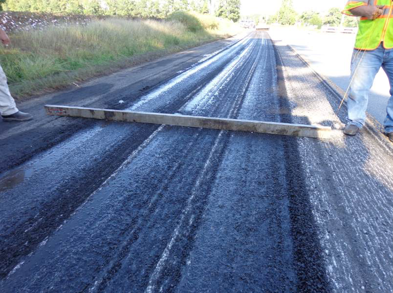
This is a decent milling job. If you don’t have automation on the milling machine telling you that you’re doing it right—and even if you do—lay a 4-foot level down across the lane. This is the best way to double-check your work behind the mill.

This is a decent milling job. If you don’t have automation on the milling machine telling you that you’re doing it right—and even if you do—lay a 4-foot level down across the lane. This is the best way to double-check your work behind the mill.

Set the Speed
One of the worst things a project manager can do is try to break the record for the number of square yards the milling crew can take out in an eight-hour shift. I know that’s a little sensationalized, but when we demand more and more productivity out of workers and machines, when we glorify how fast a crew gets a project completed over how well they performed the job, we set the crew up to take shortcuts. Instead, the project manager needs to convince the milling machine operator to take a look at the process.

Let’s start the process at the transverse joint. Because the cutter drum is round and the teeth set in a spiral pattern around it, the “line” where the cutter sets into the layer of pavement gets a 50-degree slope or curve down into it. The cutter is round so it only cuts a straight line longitudinally. It will give you a scalloped edge. To make the transverse joint straight, the milling team will want to bring in a small mill, like a two-footer, and work it directly across the lane to get the square butt joint you need for good paving afterward. You’ll perform this perpendicular cut with the two-foot mill at the beginning and end of the milling pass.

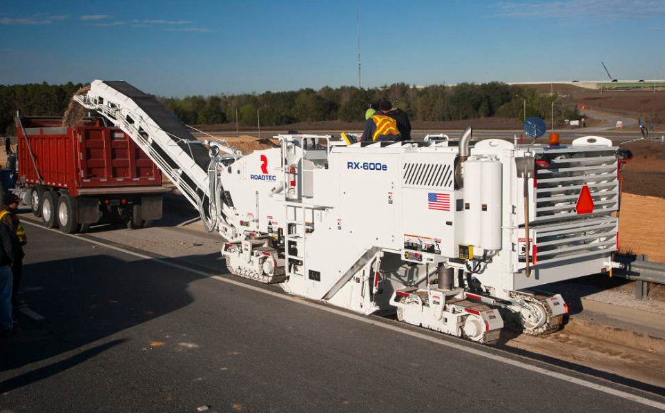
Another aspect of the milling process is filling trucks. No matter how many haul trucks are lined up to be filled, the operator must not accept the mindset of “go go go” to hurry and get rid of the trucks. Each truck should be dispatched in a timely fashion from the yard to give drivers enough time to reach the jobsite, pull in to receive a coating of release agent, drive ahead of the mill to accept millings, and then drive off to the plant for unloading once the bed is adequately filled.

Filling a truck to an adequate level means mounding the material correctly in the front, back and center of the bed without overflow. In the event of overflow, ground personnel have to step in to clean up material with shovels and/or a skid steer, wasting time and fuel.
Screen Shot 2016-01-22 at 10.11.26 PM

The milling machine operator is the one who sets the speed at the operator’s station. If he sets it too fast, the cutter drum under the machine responds unfavorably. It will gouge the teeth into the road, tearing and ripping at the layers of pavement. What the operator will see behind the machine is a mess of gouges with no discernable pattern.

What he wants to see is the herringbone pattern of all the teeth making contact and grinding out uniform lines of pavement.

Avoid Doubling, Tripling Work
As the operator looks back at the pattern behind the mill, if he sees the pretty chevron pattern and a uniform depth of the cut, he can feel confident that the paving team will have an easier time of hitting its target for yield. Quality control for depth and slope is easy enough with a 12-foot straight edge placed across the lane. See the sidebar on page xx for some safety tips on checking depth of the cut.

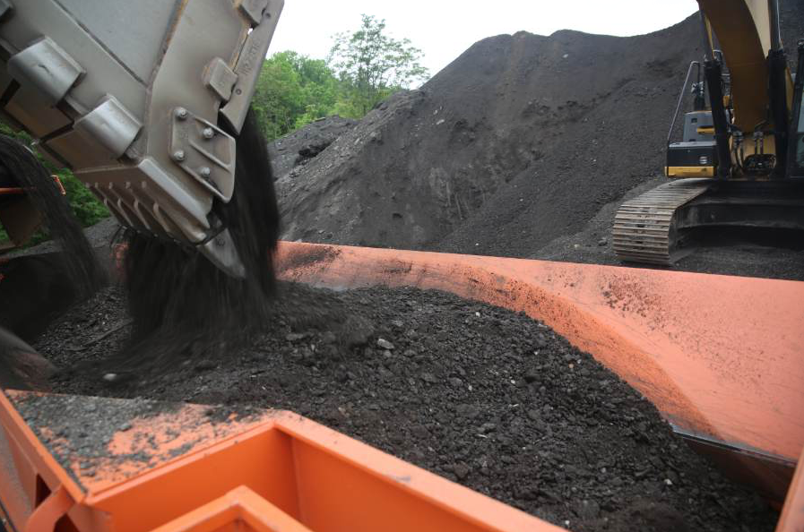
Another place to look for signs of quality is at the discharge chute. As he watches the material coming off the belt into the truck, the operator should look for chunks or clumps of material larger than millings. If it’s coming out chunky, it’s a sure sign that the mill is traveling too fast. It’s also a sign that someone else will have more work to do.
Screen Shot 2016-01-22 at 10.11.32 PM

The material from the pavement is a recyclable product that goes back to the plant for stockpiling, fractionating, screening, etc. If the product leaving the discharge conveyor is full of chunks, it will have to be crushed when it gets to the plant. That equals additional money and time not originally planned for this project, because the milling operator has not done his job correctly. This also means the pavement is left with holes and dips that will require additional mix to fill, causing new calculations for yield and possibly for production so the paving crew can get a uniform roadway.

If the project manager—or DOT inspector—sees the need, he may call for the milling crew to re-mill the surface to get it right. Doubling up on any portion of a project is a recipe for lost profit. A practice that’s gaining momentum is the use of automation for the milling crew. If the team is using automation, one operator can typically run both sides of the machine with little fear of gouging the pavement layers or putting in a trench no one wanted. If not using automation, the crew needs to have exact edges to match.

Let Trained Employees Do the Work
The project manager needs to take the milling machine operator aside to show him how the end result should appear. Instill pride of workmanship into the operator. The boss may want “more tons,” but he also wants a job well done.

One way to get the job done well is to pay attention to the machine. It will tell you when teeth need to be changed. Rather than worrying about the cost of 18 to 19 teeth today and 16 to 17 teeth tomorrow, consider the ragged cut job you’ll have if you allow teeth to wear down. By getting a uniform cut job all the way across, the surface will be set up correctly for the paving crew. Don’t be cheap—change the teeth when you need to.
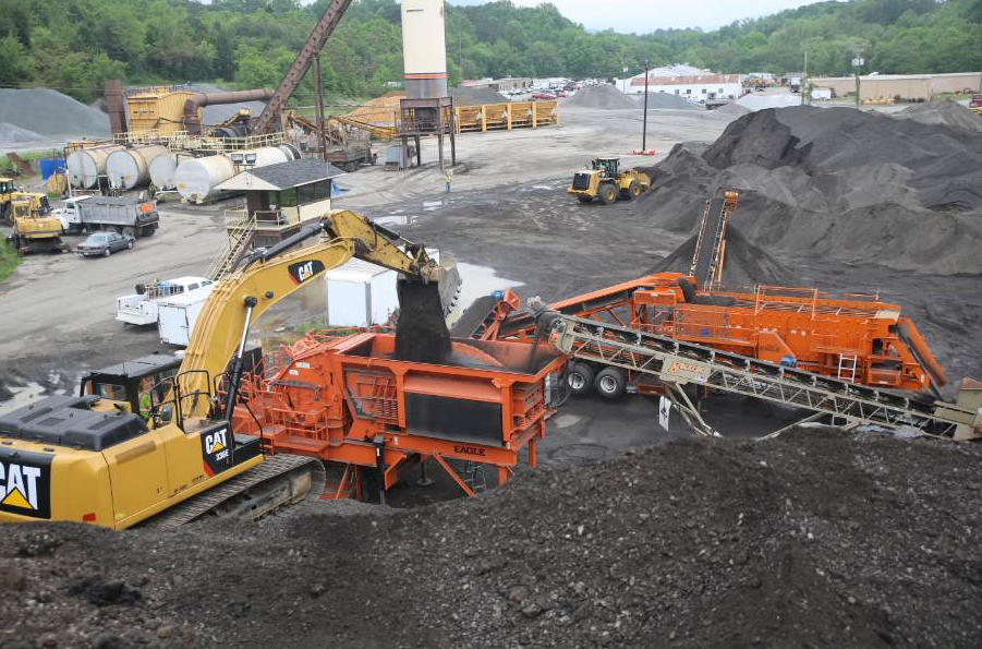
Recycling operations try to minimize the number of times material must be handled. When the milling crew sends material that needs extra handling back to the plant, it adds extra time—thus cost—to the job. Photo courtesy of Team Eagle.

Recycling operations try to minimize the number of times material must be handled. When the milling crew sends material that needs extra handling back to the plant, it adds extra time—thus cost—to the job. Photo courtesy of Team Eagle.

In some states, such as South Carolina, the problems contractors have had in the past guaranteeing that good, uniform cut across the job on a consistent basis has led the state DOT to reduce the practice of milling. They’ve turned instead to micro-milling with a 1,200-tooth cutter drum that requires a slower speed on all interstate lanes. In the state of Georgia, the DOT often specifies micro-milling, or profiling instead of milling several inches.

You just cannot profile at a high rate of speed. These states have essentially forced their own quality control upon the contractors. Rather than set yourself up for a state-mandated speed limit, set your own quality control speed and parameters, and train your equipment operators to hold true to those parameters.

When the milling crew is on the job, each member of the crew should be well versed in the operation, maintenance and safety protocol of the milling equipment. In the event the paving crew has need to touch up milled areas, make sure a member of the milling crew or a paving crew member trained in milling operation is available. You don’t want to risk an untrained operator maneuvering a $750,000 piece of machinery. Know the boundaries of the machine.

Remember that milling machines have a high center of gravity and a sensitivity to slope. There’s a slope level on the machine. If you go past it, the machine will tip over. At the least, you wreck a half-million dollar machine; at the worst, you crush workers or passing motorists.

Trained workers will keep a steady pace of milling the half lane, setting back, milling forward again, etc. They’ll keep the trucks filled to proper levels with uniform material from a well-maintained cutter drum working at a steady speed. That steady speed depends upon the surface being milled, the depth of the cut, the type of pavement, the makeup of the pavement and its structure, and more.

We can say to set the speedometer for 50 or 60 feet per minute, but even that typical pace might be too fast if removing a 12-foot-wide, 8,000-PSI PCC pavement to a depth of its rebar. The project manager then keeps a well-trained paving crew working at a steady pace behind the milling crew with haul trucks spaced to keep perishable mix arriving only as it’s needed. When a mill-and-fill project has both stages ongoing, scheduling takes on increased importance.

Despite the number of trucks lined up with or without mix, the milling machine operator can’t give in to pressure to speed up his process. The team doesn’t win if the milling machine is galloping toward an imaginary finish line. Quality will lose every time.

John Ball is the proprietor of Top Quality Paving, Manchester, N.H. For more information, contact him at (603) 493-1458.

*****

Change Depth-Check Practice
At this time, it’s common to see the ground man check the depth by inserting the ruler behind the cutter drum of the milling machine. He will approach the cutter drum housing, brush some material away with his foot, and then lean in to insert the ruler. This practice must stop.

In the event that the cutter makes contact with a large rock, with a manhole cover, a sewer cap, or with some other obstruction that the crew has not anticipated, the cutter can actually kick back, running over the worker. He could lose a foot, his leg or his life.

The better depth-check is at the back of the machine. With full communication and all ground personnel and the milling machine operator aware that the ground man is taking the depth-check, the worker can approach the back of the machine, insert the ruler in the path, and read the measurement. Please note that this type of maneuver involves communication so all relevant parties know where he is and what he’s doing. By entering the machine operator’s blindspot, the worker puts himself in danger. His safety buddy should be in direct line-of-sight with the machine operator and with the worker. If anything goes wrong, that safety buddy can sound the alarm or use the pre-arranged communication signals to get the milling machine stopped immediately.
Asphalt Test Track in Germany Tests Asphalt Strength

Car manufacturers use specially built test tracks to develop new vehicles and to test vehicles already in production. Many different track sections are needed such as uneven “torture tracks” and high speed tracks with a very smooth surface. In 1919, Opel built its first test track. Rides with a maximum speed of 87 miles per hour (140 kph) were possible on the concrete oval of almost 1 mile (1.5 km) in length close to Rüsselsheim, Germany. A bigger testing ground was constructed 1951 within the factory premises of Rüsselsheim, but it proved too small after a very short time.

Therefore, in 1964 Opel started the construction of a new testing ground in Rodgau-Dudenhofen, a small city in a woodland south of Frankfurt. Part of this new test area was a high speed course. In 1993, it was completely rehabilitated, including the subbase.

Refine with Asphalt

When Concrete Fails

In 2012, the track was renewed again and technically refined. That’s where this article begins. For this project, the track was milled and a new, strongly superelevated asphalt surface with no longitudinal joints was paved. At the same time, it was re-profiled to allow even higher car testing speeds.

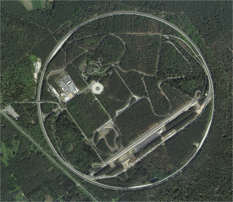
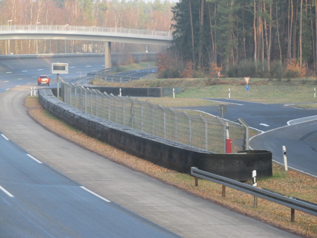
The Testing Center of the Adam Opel AG is surrounded by a circular high speed track of almost 3 miles (4.8 km). The shape of the track corresponds to an infinite straight line. That means that constant rides without side acceleration and nonstop-rides with defined operating conditions can be realized. Initially, this circuit was made of concrete with three lanes, parabolically superelevated, with a total width of 46 feet (14 m) and a radius of almost 2,500 feet (760 m). The cross slope of up to 32 degrees allowed a maximum speed of 140 mph (225 kph) without side acceleration. Six brake stops for braking tests, constructed in concrete, were located along the circumference at the inner part of the track.

Shortly after the completion of the track, defects occurred on the concrete surface at the end of the daily paving sections. Subsequently, many blow ups occurred in the following years. The smoothness worsened, the track became bumpy and the accuracy of test results suffered accordingly. The damages were mainly traced back to a bad compaction of the subbase, a poor joint maintenance, an intense use of salt during winter services, and a malfunctioning drain on the inner curb of the track. This resulted in a complete rehabilitation of the high speed track and in a reconstruction of the drainage lines on the inner curb of the track in 1993.

Within only five months, the old concrete track was broken down and recycled, the entire subbase was renewed and a hydraulically reinforced base course of 0.5 foot (15 cm) was built. In doing so, the maximum cross slope of the track was increased to 37 degrees. The three outer lanes were now paved in asphalt. The inner lane for brake tests and slow rides was made of concrete including three special concrete brakepoints. A supply and maintenance road was installed outside the track on the top of the embankment. To improve safety, two sign gantries with driver information system as well as a road illumination were added.

The construction of the lanes was carried out according to the German technical guide lines (ZTV bit-StB 84/90 and ZTVT-StB 86/90). For the upper asphalt layer, an extra stable mix using the plastomer Vestoplast as a binding agent was used. Basalt and diabase chips were employed as mineral compounds. That was 1993. Twelve years later, cracks happened.

From 2005, cracks occurred in many areas of the track. Therefore experts from the road and pavement engineering sector of TU Darmstadt examined the track. They suggested an obvious hardening of the binder was to blame. The influence of the used binding agents was discussed as another reason, but not pursued. The cracks in the track surface allowed water, thawing chemicals and oxygen into the construction, which intensified the aging process. At this time, the concrete track and the three brakepoints showed no damages. Also the joints including their tapes were almost in good condition, too. So the tasks for the rehabilitation of the high speed track in 2012 were as follows:

  1. Dismantle the road installations such as guard rails, sign gantries, metrology instrumentation, ductwork and other electrical installations
  2. Mill and re-profile the asphalt surface and binder courses of the complete track;* mill the surface course of the framing supply and maintenance road
  3. Repair the base course in the areas damaged by top-down cracks
  4. Pave a new asphalt binder course and surface course
  5. Reassemble road installations and complementing metrological devices

Upgrade the Curve

The Adam Opel AG wanted to change the curve profile in a manner that a speed of 155 mph (250 kmh) without side forces would become feasible. As with a total thickness of 8.7 inches (22 cm), the existing three-layer asphalt construction from 1993 was over-dimensioned for the load of passenger cars, the project team decided to give the track a new, steeper profile by milling. Therefore, they milled the surface course, the binder course and 1.2 to 1.6 inches (3 to 4 cm) of the base course in the central part of the cross section. In addition, they over-profiled the outer third, thereby increasing the maximum cross slope on the upper edge of the track from 37 to 40 degrees.

The high speed circuit is part of nearly every test routine in the Test Center Dudenhofen. It is highly frequented, thus needed an extremely short construction time. Construction was scheduled for the period from mid-January to the end of June 2012. For the asphalt paving an experienced team with a special paver and special rollers was essential. The paver had to produce three lanes with parabolic cross section without longitudinal joints in one flow of work. The SMB Construction International GmbH, a collective subsidiary company of the Strabag International GmbH and the Max Bögl group of companies, was awarded the project as a prime contractor. The research center for road and pavement engineering of the TU Darmstadt and the engineering office Hart Consult International GmbH under the direction of Dr. Rainer Hart were responsible for the quality control.

After the dismantling of the guard rails, a cold milling machine with a cutting width of 1 m removed the asphalt surface course and binder course, as well as parts of the asphalt base course on the entire high speed track, which is about 621,600 square feet (57.750 m²). The average milling depth was approximately 4.7 inches (12 cm). The milling was done counterclockwise. For the purpose of pre-profiling the new slope and to comply with the minimum thickness of the remaining base course, the milling depths were given in sections and checked directly behind the milling machine. Finally, a high-pressure water jet and a rotating broom were used to clean the milled area.

After the surface and binder course were removed, the repair and maintenance works were mainly carried out manually. The damaged, non-stable areas of the base course were milled; non-fixed or loose layers were loosened, washed away and cleaned. The new base course was built manually in these areas. Moreover, cracks were widened out, cleaned and grouted.

The asphalt layers were paved daily between 6:30 a.m. and 8:00 p.m.; therefore, the paver was prepared starting 5:00 a.m. Approximately 2,000 feet (600 m) of asphalt lane was paved per day. The daily joints of the surface course were always positioned offset to the daily joints of the binder course.

The project team turned their attention especially to the formation of the upper edge of the high speed track. The joint between the layers of the test track and the supply and maintenance road was designed in a special way to prevent water from entering the binder and the surface courses through this area.

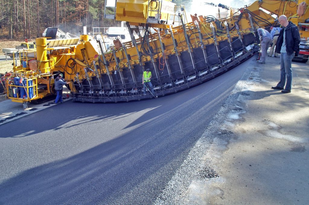
The required asphalt track with parabolic cross section and without longitudinal joints was built by means of the bridge paver from SMB Construction. This machine was designed especially for paving circuits and tracks with curved and superelevated profiles and changing radii. The asphalt mix is transported from the truck by means of a self-propelled feeder and adjustable augers to a scraper belt. A paddle chain then distributes the mix evenly in front of the screed. A microprocessor-based controller in the paver takes care of the correct position of the screed elements. Contact-free inductive sensors—joint matchers/trackers—measure both position and height, from specially developed reference rails—skis. Then, the computer controlled hydraulic cylinders deform the screed in a way that the paved layer reaches its nominal position in each area of the space curve. The data needed was exactly determined in advance and stored in the paver’s software as a digital terrain model. Simultaneously, a slope control system surveyed the inclination of the bridge girder. In parallel, a surveying team checked and recorded the paving continuously.

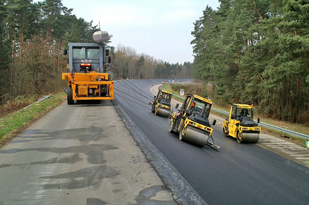
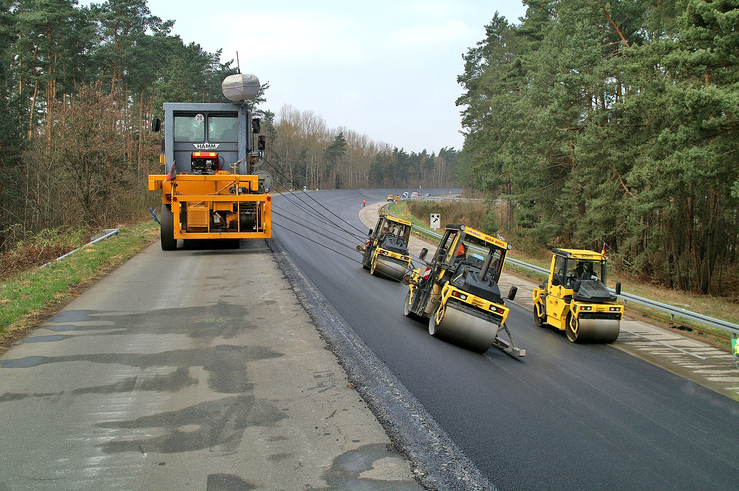
For the compaction, double vibratory rollers with specially shaped drums were used. Moreover, two rollers in the upper, steep area were each lead by a mobile winching vehicle. The roller in the shallower track section worked without winching vehicle. The use of a roller lead by a winch brings a considerable time frame of approximately 15 minutes between the paver and the breakdown compaction. This is why it might become difficult to achieve the intended degree of compaction under poor weather conditions such as low ambient temperatures or strong winds. This problem is worsened by the inclination in the top section because the rollers necessarily develop lower normal forces and thus a lower compaction effect.

Sensors were integrated into the new road surface. They permanently deliver data concerning temperature and humidity of the pavement so that these could be considered both in the testing results and to detect the road characteristics. Moreover, the new safety barrier on the upper edge was “electrified.” It was equipped with signal transmitters, which are able to inform the drivers on the track in case of an impact.

Mix It Up

Adam Opel AG demanded a long-lasting asphalt pavement with homogeneous surface. In addition, paving in steep slope required an adequate stability of the asphalt in hot, non-compacted condition.

An asphalt concrete AC 16 BS with a 4 percent void content served as binder course and repair material. As the low air voids constrain the bitumen’s natural aging process, the mix should be especially long-lasting. The use of hydrated lime as a filler stiffened the mix in hot state and had a positive influence on the asphalt layers’ weathering resistance.

A stone mastic asphalt SMA 11S, which was mixed with low void content and low tendency for segregation, was used for the surface course. As binding agent, a highly modified special bitumen was used, which, being a polymer component, not only contained SBS-elastomers, but also contained plastomers to effect better compactibility under low temperatures. The binding material’s chemical affinity to the stone was increased using a fiber additive.

Compared to the official standards, the requirements for the aggregate were increased with regard to their polishing resistance, shape, impact resistance, and the admissible over- and undersize. Moreover, the construction contract radically limited the road-building related tolerances to be found in the official standards (ZTV-Asphalt); most of the parameters were restricted to half of their value. Further parameters, such as the void filling level, were taken into the catalog of requirements and given tolerances. Some of the suppliers did not believe those requirements to be practical, thus did not submit bids. Table 1 shows some details of the spec.

In vehicle development, the test track works as a measuring system whose performance characteristics have to remain constant even over years of intensive use. This results in quality requirements beyond the standard monitoring in road construction. In particular, the steep slope of the track requires a constant asphalt consistency. Due to significantly higher costs compared to usual road construction, the risk of failure is to be minimized. This being said, an internal and external monitoring team with a site lab was installed to support the construction. Their tasks included:

  • Preparing measures (internal and external monitoring to be agreed upon)
    Exploration of suitable occurrence and suppliers for the aggregates, sampling of relevant quarries, definition of the extraction areas, sampling and optimization of the minerals processing, determination of suitable binders, inspection of different asphalt mixing plants, selection of an adequate plant close to the location and comparative analysis of the internal and external monitoring
  • Optimizing the mix proportion
    Extensive initial inspection (variation of binder contents included), verification of cold behavior and water sensitivity, calibration of the mixing unit, sample mixes, test the mix proportion and the compression regime in testing fields and definition of a final composition
  • Quality management supporting the construction
    Nondestructive density measurements to estimate the compaction success during the paving (e.g. in hot condition), asphalt analysis with submission of the results within 2 to 4 hours so that an immediate correction was possible, daily survey of the screened aggregate mixes at the plant and potential adjustment of the design, bitumen analysis and survey of the compaction of the installed layers on asphalt cores

The described activities were completed in only five months time. The design and construction followed the general technical basic rules, but with special machines and essentially higher demands on dimensional accuracy and compliance with the mix design. After all, this was the design and construction of a three-dimensional structure with an extreme cross slope of up to 79 percent and a longitudinal slope of 0 percent on the entire track.

The complex quality survey showed that it is certainly possible to drastically decrease the tolerances of the mix proportion against the specs of the basic rules (TL Asphalt-StB). Problems had to be solved on short notice and on-site. At the same time, it was rarely possible to build on experiences with comparable structures. This required a close cooperation of all team members as a top priority. This was the only possibility to respond to the tight schedule without quality losses. The users of the new track, the test drivers of the Test Center Dudenhofen as well as the technical group and the measuring group of the Technical Development Center of the Adam Opel AG in Rüsselsheim confirm that this project has been carried out with success.

Dr. Stefan Böhm is with the Road and Pavement Engineering, TU Darmstadt. Dipl. Engineering Martin Drees is with the Adam Opel AG. Dr. Gerhard Faust is formerly of Adam Opel AG. Dr. Rainer Hart is with Hart Consult International GmbH. Dr. Markus Limbach is with SMB Construction International GmbH.


For 2012, the Adam Opel AG wanted to change the curve profile of the track so speeds up to 155 mph (250 kmh) could be achieved without side forces. The existing three-layer asphalt construction from 1993 had been over-designed for the load of passenger cars, so the project team needed to mill off the layers and profile for a steeper finished surface.

Shortly after the completion of the track, defects occurred on the concrete surface at the end of the daily paving sections. Subsequently, many blow ups occurred in the following years.

They increased the maximum cross slope on the upper edge of the track from 37 degrees to 40 degrees.

German Paver

In this image, the bridge paver from SMB Construction lays the asphalt mix with an electrically heated screed. The screed consists of 17 individual bodies which are linked with the permanent screed plate. 17 hydraulic cylinders control the deformation of the screed; the cylinders are controlled by automation. This machine was designed especially for paving circuits and tracks with curved, superelevated profiles and changing radii. Here’s how it works:

  1. The asphalt mix is transported from the truck by means of a self-propelled feeder and adjustable augers to a scraper belt.
  2. A paddle chain then distributes the mix evenly in front of the screed.
  3. Contact-free inductive sensors—trackers—measure both position and height, from specially developed reference rails—skis.
  4. A micro-processor-based controller—automation—positions the computer controlled hydraulic cylinders to deform the screed in a way that the paved layer reaches its nominal position in each area of the space curve. (For the Adam Opel AG project, the data was determined in advance and stored in the paver’s software as a digital terrain model.)
  5. Simultaneously, a slope control system surveys the inclination of the bridge girder. (For the Adam Opel AG project, a surveying team checked and recorded the paving continuously for quality control.)

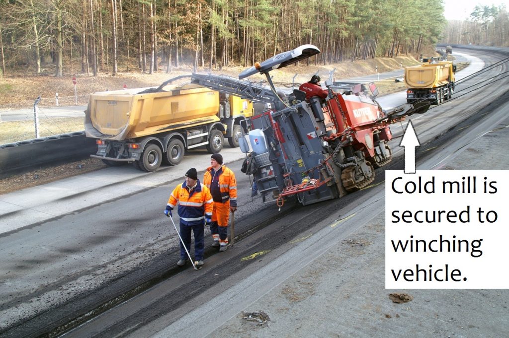
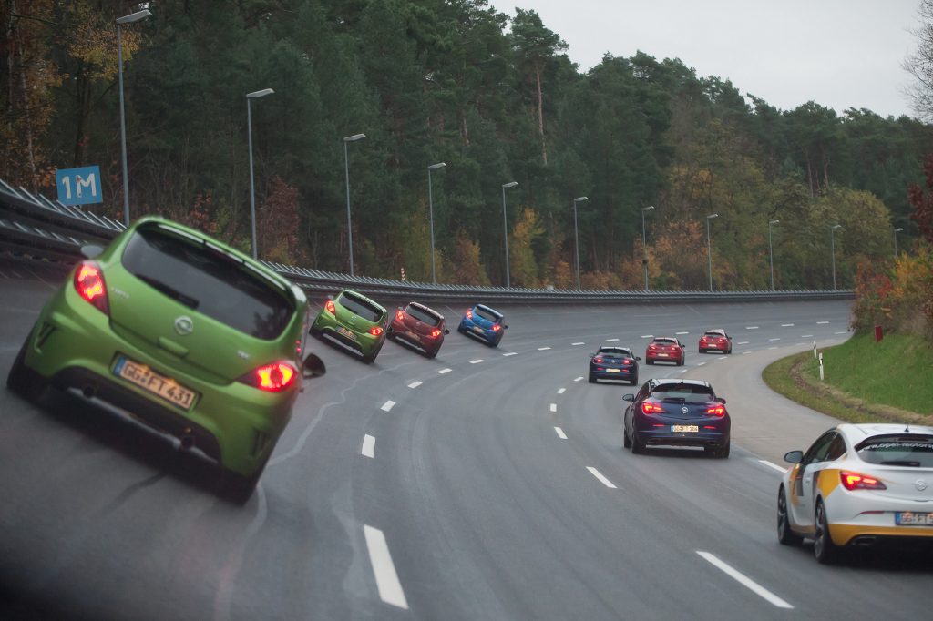
German AerialThe Testing Center of the Adam Opel AG in Rodgau-Dudenhofen, Germany, is surrounded by a circular high speed track of 2.98 miles (4.8 km). The shape of the track corresponds to an infinite straight line.German MillingFor the purpose of pre-profiling the new slope and to comply with the minimum thickness of the remaining base course, the milling depths were given in sections and checked directly behind the milling machine. Cross slopes of more than 9 degrees made a winching vehicle necessary that held the machine to enable milling in the banked track.KONICA MINOLTA DIGITAL CAMERATo avoid roller marks, the edges of the roller drums should exert no pressure on the freshly compacted asphalt. For this reason, the upper rollers were equipped with a slope control. A computer in the winching vehicle controlled the height-adjustable hold point in a manner that the rollers permanently drove orthogonally to the surface.German DrivingTire walls and safety fences ensure the safety of drivers and staff who stay along the track during the testing. After the rehabilitation, the test drivers from Opel are highly satisfied with the quality of the new track.

German Electric

Table 1: Specification of surface course and binder course

Binder Course Surface Course
Asphalt Mix Type AC 16 BS SMA 11S
Bitumen 70/100 Olexobit SMA; PmB 40/100-65 A
Softening point
ring and sphere
47.6 °C 71.6 °C
Needle penetration 81 (1/10 mm) 50 (1/10 mm)
Additives hydrated lime N/A
Void content 4% 2.2%
Technical specifications TL Asphalt-StB 07, ZTV Asphalt-StB 07 and further technical requirements